Download presentation
Presentation is loading. Please wait.

1
Air Refueling Procedures Brief
UPDATED MARCH 2012

2
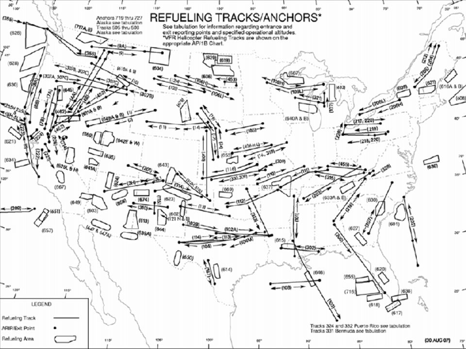
FTI Procedures Filing Rendezvous Types and Procedures
AP1B GP Rendezvous Types and Procedures RV Alpha (Anchor) RV Delta (Point Parallel) RV Golf (En Route) Checklist Management Communications Plan Air refueling area RVIP/RVCP (ARIP/CP/CT) Offset FMS Setup Seagull / RVIP-RVCP line Recommended PFD Setup Air refueling altitude, Air refueling track, Air refueling speeds Overrun and Under-run Procedures Closure Closure from ½ mile to Contact Positions Boom Limits Demo Breakaway Procedures Role Reversal Procedures Recovery
 RV Delta (Point Parallel) RV Golf (En Route) Checklist Management. Communications Plan. Air refueling area. RVIP/RVCP (ARIP/CP/CT) Offset. FMS Setup. Seagull / RVIP-RVCP line. Recommended PFD Setup. Air refueling altitude, Air refueling track, Air refueling speeds. Overrun and Under-run Procedures. Closure. Closure from ½ mile to Contact Positions. Boom Limits Demo. Breakaway Procedures. Role Reversal Procedures. Recovery.")
3
Filing AP1 B Chapter 4 AR example GP Chapter 4 Flight plan example

4
AP1 B Track Name/Direction Navigation Comm/RV plan
AR Altitudes (Block) Scheduling unit (preflight planning) ARTCC (SODAR) COMMUNICATION/RENDEZVOUS PLAN a. Primary UHF b. Backup UHF c. APN 69/134/135 Settings (Beacon) d. APX 78/Encode/Decode (Transponder) e. TACAN Channels Receiver/Tanker
 Scheduling unit (preflight planning) ARTCC (SODAR) COMMUNICATION/RENDEZVOUS PLAN. a. Primary UHF. b. Backup UHF. c. APN 69/134/135 Settings (Beacon) d. APX 78/Encode/Decode (Transponder) e. TACAN Channels Receiver/Tanker.")
5
AP1 B Track Name/Direction Navigation Comm/RV plan
AR Altitudes (Block) Scheduling unit (preflight planning) ARTCC (SODAR) COMMUNICATION/RENDEZVOUS PLAN a. Primary UHF b. Backup UHF c. APN 69/134/135 Settings (Beacon) d. APX 78/Encode/Decode (Transponder) e. TACAN Channels Receiver/Tanker
 Scheduling unit (preflight planning) ARTCC (SODAR) COMMUNICATION/RENDEZVOUS PLAN. a. Primary UHF. b. Backup UHF. c. APN 69/134/135 Settings (Beacon) d. APX 78/Encode/Decode (Transponder) e. TACAN Channels Receiver/Tanker.")
6
DD175

8
Rendezvous RV Delta (Point Parallel)
")
9
Rendezvous: RV Golf (Enroute)
")
10
AR Training Flight Overview
Ground Ops- Per Formation FTI chapter. Takeoff and depart to area as a formation. If weather precludes section takeoff, use established rendezvous procedures to effect rejoin in the area. Tanker to CP, Clears Receiver to rendezvous altitude and to IP. Checklist Comm Plan Tanker Procedures. Receiver Procedures.

11
Checklists Rendezvous /Pre-descent Checklist
1. Radios …………………………..Set (P,CP) 2. Crew..………………………Notified (P,CP) 3. Radar..………………………..Standby (CP) 4. TAS……………… As Req (CP) 5. Altimeters..…………………As Req (P,CP) 6. TACAN A/A……………….....As Req (CP) 7. MARSA (Tanker)………………Declare (P) Prep for Contact (Completed before 1/2 mile) 1. Crew……………...Ready for Refueling (P) 2. Exterior Lights………………..As Req (CP) 3. Autopilot……………....Disengaged (P,CP) 4. Transponder…………………..…..Off (CP) 5. Seat Height……… Adjust as req (P,CP) Simulated Contact 1. Position…………………Monitor (P,CP,OB) After Air Refueling 1. After Refueling Report………..As Req (CP) 2. External Lights ………………..As Req (CP) 3. Transponder ……………………….Set (CP) 4. TAS……………………………As Req (CP) 5. Altimeters………………………..Set (P,CP) 6. Crew …………………………...Notified (P)
 2. Crew..………………………Notified (P,CP) 3. Radar..………………………..Standby (CP) 4. TAS……………… As Req (CP) 5. Altimeters..…………………As Req (P,CP) 6. TACAN A/A……………….....As Req (CP) 7. MARSA (Tanker)………………Declare (P) Prep for Contact (Completed before 1/2 mile) 1. Crew……………...Ready for Refueling (P) 2. Exterior Lights………………..As Req (CP) 3. Autopilot……………....Disengaged (P,CP) 4. Transponder…………………..…..Off (CP) 5. Seat Height……… Adjust as req (P,CP) Simulated Contact. 1. Position…………………Monitor (P,CP,OB) After Air Refueling. 1. After Refueling Report………..As Req (CP) 2. External Lights ………………..As Req (CP) 3. Transponder ……………………….Set (CP) 4. TAS……………………………As Req (CP) 5. Altimeters………………………..Set (P,CP) 6. Crew …………………………...Notified (P)")
12
Communications Plan Interplane --- 140.525
(Pri)Interplane (Sec) A/A TACAN--- 29Y receiver / 92Y tanker Ensure TACAN is set To AA.
Interplane (Sec) A/A TACAN--- 29Y receiver / 92Y tanker. Ensure TACAN is set To AA.")
13
Simulated Air Refueling Area
Seagull Central working area. Can coordinate any altitude block. Accept MARSA and inform Seagull of multiple breakups and rendezvous. Ensure lateral and vertical boundaries honored. If needed can coordinate two blocks and designate longer IP/CP line or designate different IP/CP for alternate seagull procedures.

14
RVCP CRP 115/38 OFFSET RVIP CRP 115/55

15
FMS SETUP INITIAL POINT CRP 115/55 CONTROL POINT CRP 115/38
HOLD POINT CRP 115/38 -- DISCONTINUITY -- SEAGULL BOUNDARIES

16
RECOMMENDED PFD DISPLAY
PRIMARY NAV – FMS PRESET – VOR TUNED TO CRP #1 NEEDLE – TCN (AIR-AIR) #2 NEEDLE – VOR2 (DME FROM CRP) COURSE – DETERMINED BY FMS SPEED – A/R 150 TANKER / 180 SELECTED RECEIVER HEADING – A/R OB OR IB WIND CORRECTED PSA – TANKER ALTITUDE, SET PRIOR TO JOIN
 #2 NEEDLE – VOR2 (DME FROM CRP) COURSE – DETERMINED BY FMS. SPEED – A/R 150 TANKER / 180 SELECTED RECEIVER. HEADING – A/R OB OR IB WIND CORRECTED. PSA – TANKER ALTITUDE, SET PRIOR TO JOIN.")
17
Set up intercept between the RVCP and RVIP (CP in Green).
USE 2 mile OFFSET on FLT PLAN page. 3. Inhibit FMS sequence. 4. Verify offset on Progress Page. OFFSET COURSE

18
Overrun/ Under-run Procedures
Tanker airspeed – Receiver airspeed – Receiver will then call “terminate overrun procedures” when within NM and below the tanker UNDER-RUN Receiver will then call “terminate under-run procedures” at NM and below the tanker Increase to180KTS Decrease to 150KTS ’ Decrease to 140KTS Sets Max Cruise Power until 1NM ’

19
Receiver Closure Airspeed/ Altitude Schedule
3 NM 180 KIAS 1000’ below tanker 2 NM 1 NM ½ NM 170 KIAS 500’ below tanker .3 NM 160 KIAS 300’ below tanker Pre-contact 150 KIAS 15’ below tanker Receiver Closure Airspeed/ Altitude Schedule 3 NM KIAS below tanker 2 NM 1 NM ½ NM .3 NM Pre-contact 500’ below .5 DME behind 1000’ below 1 DME behind

20
.3 DME /300 FT below

21
Receiver will stabilize 50’ behind on 30º bearing line
Precontact Position PRECONTACT Receiver will stabilize 50’ behind on 30º bearing line

22
Closure 3 Precontact Precontact

23
KC-135 verse KC-10 position lights
Contact Position CONTACT KC-135 verse KC-10 position lights

24
KC-135 verse KC-10 position lights
Contact Position CONTACT KC-135 verse KC-10 position lights

25
Closure 4 Contact Contact

26
Boom Limits KC-135 KC-10 Up/Down 30º ± 10 Left/Right ±10º
Fore/Aft – 18.3 ft KC-10 Up/Down º ± 10 Left/Right ±19º Fore/Aft – 21 ft

27
Boom Limits Demo Right Limit demo
The visual indications of the right position include lining up directly behind the tanker right engine inboard exhaust stack, and the tanker tail fixed on the top edge of the receiver windscreen. The tanker vortices tend to push the receiver aircraft to the center. Inexperienced pilots will over correct when trying to return to centerline behind the tanker. Opposite aileron to the direction of drift back to center may be necessary to slow down the rate of return and avoid an overshooting oscillation. A technique for moving from center to the left or right is to ratchet the aircraft slowly to the outer limit then stabilize.

28
Boom Limits Demo Left Limit demo
The visual indications of the left position include lining up directly behind the tanker’s left engine inboard exhaust stack, and the tanker tail fixed on the top edge of the receiver windscreen. The tanker vortices tend to push the receiver aircraft to the center. Inexperienced pilots will over correct when trying to return to centerline behind the tanker. Opposite aileron to the direction of drift back to center may be necessary to slow down the rate of return and avoid an overshooting oscillation. A technique for moving from center to the left or right is to ratchet the aircraft slowly to the outer limit then stabilize.

29
Breakaway Procedures “BREAKAWAY, BREAKAWAY, BREAKAWAY”
Either aircraft in the formation can call a Breakaway. TANKER PROCEDURES Increase power Start a climb but do NOT decrease airspeed to lower than 150KTS If in a turn, maintain established bank angle Turn on Rotating Beacons RECEIVER PROCEDURES Receiver Pilot Actuate autopilot/boom disconnect Power to Idle Start rate of descent away from Tanker Transition to instruments Props full forward if necessary to assure safe separation Receiver Co-pilot Actuate autopilot/boom disconnect switch Turn on TAS Keep Visual of Tanker confirming aircrafts are well clear

30
Role Reversal Procedures
Tanker Turn to receivers’ reciprocal heading With 3NM separation is attained with increasing DME. Coordinate a altitude swap Descend to 1000’ below A/R altitude Receiver Maintain present airspeed and altitude till 3NM with increasing DME is attained Climb to A/R altitude When both aircraft report level at their respective altitudes, the “New tanker” will proceed to the ARCP. The “New Receiver” will proceed to the RVIP and give his simulated 15 min call. The procedure for a RV Delta (point parallel rendezvous) is then initiated
 is then initiated.")
31
QUESTIONS?

Similar presentations


 Flight Crew Procedures>")


>")


 Air Refueling Procedures Brief>")


 Flight Refueling Limited.>")

