Download presentation
Presentation is loading. Please wait.

1
PHYSICAL LAYER

2
General Physical Characteristics
Support for up to 64 nodes Node removal without severing trunk line and under power. Protection from wiring errors. Reverse wiring protection circuitry built into devices. Selectable data rates: 125, 250, 500 K baud Not required to support all Data rates trade speed for distances Trunk line-drop line topology Branching allowed on drops Allows zero node separation 4

3
General Physical Characteristics
Twisted pair, low loss, low delay cable Use of sealed or open connectors Support of both (opto)isolated and non-isolated devices Separate power bus contained in the cable Support of both network-powered and self-powered devices High current capability (thick and flat cable supports up to 8 amps) Power taps that allow the connection of several power supplies. NOTE: Power Taps are only needed where power supplies are added to network outside of a sealed enclosure. Most power connections are made inside the main control cabinet using ordinary terminal strips. 5
isolated and non-isolated devices. Separate power bus contained in the cable. Support of both network-powered and self-powered devices. High current capability (thick and flat cable supports up to 8 amps) Power taps that allow the connection of several power supplies. NOTE: Power Taps are only needed where power supplies are added to network outside of a sealed enclosure. Most power connections are made inside the main control cabinet using ordinary terminal strips. 5.")
4
DeviceNet Cable Highliights
Bare Blue White Red Black +24VDC ( V+ ) CAN-H Shield CAN-L +0VDC ( V- ) 5 Conductors, 1 pair for 24 Volts DC power, 1 pair for CAN communication, 1 Shield Maximum current capability for 24 Volts DC in thick and flat cable is 8 amps. However no more than 4 amps is permitted in thick cable per NEC Class 2 requirements. ( North America Only ) Maximum current capability for 24 Volts DC in thin wire is 3 amps.
 CAN-H. Shield. CAN-L. +0VDC ( V- ) 5 Conductors, 1 pair for 24 Volts DC power, 1 pair. for CAN communication, 1 Shield. Maximum current capability for 24 Volts DC in thick. and flat cable is 8 amps. However no more than 4 amps is. permitted in thick cable per NEC Class 2 requirements. ( North America Only ) Maximum current capability for 24 Volts DC in thin wire. is 3 amps.")
5
Topology P/S Terminator Tap Terminator Trunk Daisy Chain max 20 feet
Trunk Distance Terminator Tap Terminator Trunk Node Node P/S Daisy Chain Node Node max 20 feet Node Trunk Length Node Node Node Node Node Node Branching Drop Zero Drop Short Drops 6

6
Termination Resistors
Termination resistors are 120 or 121 Ohms, 1/4 Watt They MUST be placed at each end of the trunk line between white and blue wires. There are both open and sealed versions

7
DeviceNet Physical Media Terms
“Trunk” and “Drops” are topology terms. The trunkline is the “backbone” of your network. Drops serve as physical connection mechanisms to the trunkline. Drop length up to 20 feet. There are 3 types of cables: Thick, Flat, and Thin Thick & Flat cables are rated for 8 amps of current Thin cable is rated for 3 amps of current All types of cable can be used for “Trunk” Discusses the difference of “thick” and “thin” cables vs. “trunk” and “drop” in the context of a bus topology.

8
Cable Budgets - Thick Trunk
Data Rates Kbaud Kbaud Kbaud Trunk Distance m (1640 ft) m (820ft) m (328 ft) Max. Drop Length 20 ft 20 ft 20 ft Cumulative Drop 512 ft 256 ft 128 ft Number of nodes 7
 250m (820ft) 100m (328 ft) Max. Drop Length 20 ft 20 ft 20 ft. Cumulative Drop 512 ft 256 ft 128 ft. Number of nodes")
9
Cable Budgets - Thin Trunk
Data Rates Kbaud Kbaud Kbaud Trunk Distance m (328 ft) m (328 ft) 100m (328 ft) Max. Drop Length 20 ft 20 ft 20 ft Cumulative Drop 512 ft 256 ft 128 ft Number of nodes
 100m (328 ft) 100m (328 ft) Max. Drop Length 20 ft 20 ft 20 ft. Cumulative Drop 512 ft 256 ft 128 ft. Number of nodes")
10
Cable Budgets - Flat Trunk
Data Rates Kbaud Kbaud Kbaud Trunk Distance m (1378 ft) m (656 ft) 75m (246 ft) Max. Drop Length 20 ft 20 ft 20 ft Cumulative Drop 512 ft 256 ft 128 ft Number of nodes 7
 200m (656 ft) 75m (246 ft) Max. Drop Length 20 ft 20 ft 20 ft. Cumulative Drop 512 ft 256 ft 128 ft. Number of nodes")
11
Micro Quick Disconnect
Connectors Supported Mini Quick Disconnect 18mm Micro Quick Disconnect 12mm “Terminal Strip” Style Connector Cable 15

12
Sealed T-Taps Tee Tap Field Installable trunk line connectors
Keyed left & right Field Installable trunk line connectors screw type Trunk line segments molded minior micro connectors various lengths Drop lines mini or micro molded connectors up to 20ft mini, micro or pigtail at sensor 16

13
Insulation Displacement Connector (IDC) Used for KwikLinkFlat Cable
• Requirements – Modular – Low cost – Minimal installation labor – Compact package – Compatible with existing media – NEMA 6P and 13, IP 67 enclosure rating

14
Multi-Port Sealed Media
DevicePort Multiport Tap micro quick disconnects various configurations DeviceBox Multiport Tap cord grip 2, 4, 8 grips Drop Trunk DeviceBox™ (to Trunk) DevicePort™ Drop Drop
 DevicePort™ Drop. Drop.")
15
Typical Sealed-Style Taps
Tee Taps Field Installable trunk line connectors -screw type -crimp type Trunk line segments -molded mini-connectors Drop lines - molded connectors - 0 to 6 m (20 ft.) - mini or micro at device Multiport Taps 28
 - mini or micro. at device. Multiport Taps. 28.")
16
Open Style Taps Trunk Dropline Open Open Open Open Style Style Style
Zero length drop using 1787-Plug10R with probe cable support Dropline Open Style Device Open Style Device Open Style Device Open Style Device Sealed Control Enclosure 18

17
Thick Cable Description
Signal pair (#18), blue/white Power pair (#15), black/red Foil/braid shield with drain wire(#18) PVC/nylon insulation on power pair Industrial temperature range Storage: -40o C to +85oC Operating: -20o C to +60o 8A derate linearly to 0A at 80o C High flexure capability Flame resistant, UL Oil Res. II 0.480 inch diameter 19
, blue/white. Power pair (#15), black/red. Foil/braid shield with drain wire(#18) PVC/nylon insulation on power pair. Industrial temperature range. Storage: -40o C to +85oC. Operating: -20o C to +60o 8A. derate linearly to 0A at 80o C. High flexure capability. Flame resistant, UL Oil Res. II inch diameter. 19.")
18
DeviceNet Thick Cable Beldfoil Aluminum/Polyester Shield Vinyl Jacket
.480” O.D. Blue & White Data Pair Datalene Insulation Polypropylene Fillers 18 AWG. Tinned and Stranded Copper Conductors 15 AWG. Tinned and Stranded Copper Conductors 65% Coverage Tinned Copper Braid Shield Stranded Drain Wire Tinned Copper 18 AWG. Thick Cable Belden AB number Grey PVC 3082A YR-29790 Yellow CPE 3083A YR-39659 Red & Black DC Power Pair PVC/Nylon Insulation 20

19
Thin Cable Description
Signal pair (#24), blue/white Power pair (#22), black/red Foil/braid shield with drain wire(#22) PVC/nylon insulation on power pair Industrial temperature range Storage: -40o C to +85oC Operating: -20o C to +70o 1.5A derate linearly to 0A at 80o C High flexure capability Flame resistant, UL Oil Res. II 0.270 inch diameter 21
, blue/white. Power pair (#22), black/red. Foil/braid shield with drain wire(#22) PVC/nylon insulation on power pair. Industrial temperature range. Storage: -40o C to +85oC. Operating: -20o C to +70o 1.5A. derate linearly to 0A at 80o C. High flexure capability. Flame resistant, UL Oil Res. II inch diameter. 21.")
20
DeviceNet Thin Cable Beldfoil Aluminum/Polyester Shield
Vinyl or CPE Jacket .270” O.D. Polypropylene Fillers Blue & White Data Pair Datalene Insulation Overall Mylar Tape 24 AWG. Tinned and Stranded Copper Conductors 22 AWG. Tinned and Stranded Copper Conductors Stranded Drain Wire Tinned Copper 22 AWG. 65% Coverage Tinned Copper Braid Shield Red & Black DC Power Pair PVC/Nylon Insulation Thin Cable Belden AB number Grey PVC 3084A YR-29832 Yellow CPE 3085A YR-39660 22

21
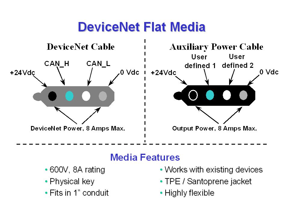
KwikLink 4-wire Flat Cable

23
Power Bus Capabilities
Single & multiple supply configurations High current capability by using multiple power supplies. Easy to meet supply specifications DNPS by Rockwell Automation is worlds only class 2, DeviceNet certified, 5.25 amp power supply. Power supplies should be dedicated to DeviceNet cable power ONLY!! 10

24
NETWORK GROUNDING V- ( Black Wire ) and Shield ( Bare Wire ) MUST be connected to a good earth ground at only one location on a DeviceNet System. Signal . Signal . Shield . V- V+ Power Tap . . V- V+ 24 VDC Power Supply

25
Single Supply Configuration
up to 500 m up to 500 m up to 500 m N32 N1 power supply N33 N64 Characteristics and Advantages Power supplies can be located anywhere on the network Must consider IR losses along cable Greater current than most comparable networks Up to 8 amps (NEC limits to 4 amps) Power supplies are standard, low cost models 13
 Power supplies are standard, low cost models. 13.")
26
Two Supply Configuration ( Current Boost )
up to 500 m N1 Power Supply N32 N33 Power Supply N64 Characteristics and Advantages Loads shared by supplies so same low cost supplies are used Substantially more current Still 8 amp limit on any branch of the trunk ( NEC limit of 4 Amps) Supplies can be located anywhere (consider IR losses) 14
 Supplies can be located anywhere (consider IR losses) 14.")
27
Topology for Power Along the Bus
Optional Second Supply 24 V Power Supply 24 V Power Supply Node Node Node Node V+ Power Conductor V- Power Conductor CAN-H, CAN-L, Shield 11

28
Power Utilization of Devices
All devices have a source voltage range of 11 VDC to 25VDC. Some devices will draw more current as the source voltage drops. All devices on a DeviceNet network will draw at least 50 mili-amps of current off of the 24VDC network power. This is because all products, regardless of type, at the minimum will have their tranceiver circuitry powered from the network power. Some devices are designed to draw all of their power off of the network power through the DeviceNet connection entirely. Examples of these type of products include Series 9000 Photoeyes, DeviceLinks and an all input ArmorBlock. Some devices will have their power requirements satisfied by another source of current such as external AC voltage or DC voltage through terminal strips. Examples of these type of products include the DTAMPlus, FlexI/O and the Bulletin 160 drive. The last category of products are those with outputs driving AC loads or higher current DC loads. These products will have tranceivers and electronics powered by the DeviceNet network power, but the output circuitry will be powered off of an external connector or terminal strip. A classic example device is an ArmorBlock with 2 or 4 DC outputs. In this case a 3 pin mini connector is provided to connect in a source of 24 VDC to power the output circuitry ONLY.

29
Common Mode Voltage An easy way to measure for Common Mode Voltage problems is to go the the farthest ends of the network and measure between the Red V+ and Black V- wires. This voltage should NEVER be less than 15 Volts.

30
Typical System Connections
Normal Control Enclosure +24V 0V Power Supply V+ Scanner Phoenix Connector CAN-H SHLD CAN-L Trunk Line V- Terminal Strip KFD/PCD Phoenix Connector Earth Ground

31
Return to DeviceNet Roadmap
Click on the underlined text to Return to DeviceNet Roadmap

Similar presentations