Download presentation
Presentation is loading. Please wait.

1
Chapter No-3 STEAM AND STEAM BOILER Marks-20

2
C404.3-Demonstrate boilers and determine steam properties by using Mollier chart and steam table.

3
Generation of steam at constant pressure
Steam and steam boiler Generation of steam at constant pressure Consider 1 kg of ice in a piston -cylinder arrangement as shown. it is under an Absolute Pressure say P bar and at temperature –t 0 C ( below the freezing point).
.")
4
Keeping the pressure constant, the gradual heating of the ice leads to note the following changes in it, These are represented on a t-h diagram on heating, the temperature of the ice will gradually rises from p to Q i.e from – t C till reaches the freezing temperature 0.

5
Adding more heat, the ice starts melting without changing in the temperature till the entire ice is converted into water from Q to R. The amount of heat during this period from Q to R is called Latent heat of fusion of ice or simply Latent heat of ice.

6
Continuous heating raises the temperature to its boiling point t C known as Saturation Temperature. The corresponding pressure is called saturation pressure. it is the stage of vaporization at bar atmospheric pressure (760mm of hg at 100'C).
..")
7
As pressure increases, the value of saturation temperature also increases. The amount of heat added during R to S is called Sensible Heat or Enthalpy of Saturated Water or Total Heat of Water (h, or h "' ).
..")
8
During the process, a slight increase in volume of water (saturated water) may be noted. The resulting volume is known as Specific volume of Saturated Water (Vf or vW).
..")
9
On further heating beyond S, the water will gradually starts evaporate and starts convert it to steam, but the temperature remains constant. As long as the steam is in contact with water, it is called Wet Steam or Saturated Steam.

10
(e) On further heating the temperature remains constant, but the entire water converts to steam. But still it will be wet steam. The total heat supplied from OOC is called Enthalpy of Wet Steam (h wet). The resulting volume is known as Specific Volume of Wet Steam (v wet)
. The resulting volume is known as Specific Volume of Wet Steam (v wet).")
11
(f) On further heating the wet steam, the water particles, which are in suspension, will start evaporating gradually and at a particular moment the final particles just evaporates. The steam at that moment corresponding to point T is called Dry Steam or Dry Saturated Steam.

12
The resulting volume is known as Specific Volume of Dry Steam (vg)
The resulting volume is known as Specific Volume of Dry Steam (vg). This steam not obeys the gas laws. The amount of heat added during S to T is called Latent Heat of Vaporization of Steam or Latent Heat of Steam (hfg). During the process, the saturation temperature remains constant.
. This steam not obeys the gas laws. The amount of heat added during S to T is called Latent Heat of Vaporization of Steam or Latent Heat of Steam (hfg). During the process, the saturation temperature remains constant.")
13
The total heat supplied from O'C is called Enthalpy of Dry Steam (hg).
(g) On further heating beyond point T to U the temperature starts from ts to tu, the point of interest. This process is called Super heating. The steam so obtained is called Super Heated Steam
 On further heating beyond point T to U the temperature starts from ts to tu, the point of interest. This process is called Super heating. The steam so obtained is called Super Heated Steam.")
15
The point a represents the initial condition of water at 0◦c and pressure P (in bar ) as shown in fig. Line ABCD shows the relation between temp and heat at a specific pressure of p(in bar).
.")
16
During the formation of the superheated steam, from water at freezing point , the heat is absorbed in the following three stages The heating of water up to boiling temperature or saturation temperature (t) is shown by ab in fig.
 is shown by ab in fig.")
17
the heat absorbed by the water is AP , known as sensible heat or liquid heat or total heat of water.
The change of state from liquid to steam is shown by BC. The heat absorbed during this stage is PQ, known as latent heat of vaporization

18
The superheating process is shown by CD
The superheating process is shown by CD.The heat absorbed during this stage is QR, known as heat of superheat. Similarly, a family of curves may be drawn for different pressures as shown in the fig.

19
The line passing through the points A,B,E,K is known as saturated liquid line which forms boundary line between water and steam. Similarly , a line passing Through dry steam points L,F,C is known as dry saturated steam line which forms boundary line between wet and superheated steam. It may be noted that from the fig., that when the pressure and saturation temperature increases , the latent heat of vaporization decreases. It becomes zero at a point (N) where liquid and dry steam line meets. This point N is known as the critical point .
 where liquid and dry steam line meets. This point N is known as the critical point .")
20
The temperature corresponding to critical point N is known as critical temperature and the pressure is known as critical pressure. For steam , the critical temperature is ◦c and critical pressure is bar.

21
Wet steam: when the steam contains moisture or particles of water in suspension , it is said to be wet steam. Dry saturated steam: when wet steam is further heated and it does not contain any suspended particle of water, it is known as dry saturated steam. Superheated steam: when the dry steam is further heated at a constant pressure, thus raising its temperature, it is said to be superheated steam. Since the pressure is constant therefore volume of superheated steam increases, it may be noted that the volume of 1 kg of superheated steam is considerably greater than the volume of 1 kg of dry saturated steam at same pressure.

22
Dryness fraction or quality of wet steam: it is the ratio of the mass of actual dry steam ,to the mass of same quantity of wet steam. It is generally denoted by ‘x’ Mathematically, X= mg = mg mg + mf m Mg= mass of actual dry steam Mf= mass of water in suspension M = mass of wet steam

23
Sensible heat of water: it is amount of heat absorbed by 1kg of water , when heated at a constant pressure, from the freezing point (0◦c)to the temperature of formation of steam, i.e. saturation temp. Latent heat of vaporization: it is amount of heat absorbed to evaporate 1 kg of water , at its boiling point or saturation temperature without change of temperature. It is denoted by h(fg). The latent heat of steam is 2257 kJ/kg at atmospheric pressure.
. The latent heat of steam is 2257 kJ/kg at atmospheric pressure.")
24
Enthalpy or total heat of steam: it is amount of heat absorbed by water from freezing point to saturation temperature plus heat absorbed during evaporation. enthalpy= sensible heat+ latent heat It is denoted by h(g) For wet steam h= h(f)+ x h(fg) Dry steam h=h(g)= h(f)+h(fg) Superheated steam h(sup)= total heat for dry steam heat for superheated steam . =h(f)+h(fg)+Cp(t sup –t) =h(g)+Cp(t sup- t) Cp= mean specific heat at constant pressure for superheated steam t sup= temp. of superheated steam t= saturation temp at the given constant pressure. The difference (t sup - t) is known as degree of superheat.
 For wet steam h= h(f)+ x h(fg) Dry steam h=h(g)= h(f)+h(fg) Superheated steam h(sup)= total heat for dry steam + heat for superheated steam . =h(f)+h(fg)+Cp(t sup –t) =h(g)+Cp(t sup- t) Cp= mean specific heat at constant pressure for superheated steam. t sup= temp. of superheated steam. t= saturation temp at the given constant pressure. The difference (t sup - t) is known as degree of superheat.")
25
Specific volume of steam
It is the volume occupied by the steam per unit mass at a given temperature and pressure. It is expressed in m3/kg.

26
Classification of boilers
1. Horizontal, Vertical or Inclined Boiler. -If the axis of the boiler is horizontal, the boiler is called horizontal, -If the axis is vertical, it is called vertical boiler and -If the axis is inclined it is called as inclined boiler.

27
Classification of boilers
2. Fire Tube and Water Tube -In the fire boilers, the hot gases are inside the tubes and the water surrounds the tubes. Examples: Cochran, Lancashire and Locomotive boilers.

28
Classification of boilers
-In the water tube boilers, the water is inside the tubes and hot gases surround them. Examples: Babcock and Wilcox, Yarrow boiler etc.

29
Classification of boilers
3. Externally fired and internally fired The boiler is known as externally fired if the fire is outside the shell. Examples: Babcock and Wilcox boiler - In case of internally fired boilers, the furnace is located inside the shell. Examples: Cochran, Lancashire boiler etc.

30
Classification of boilers
4. Forced circulation and Natural Circulation -In forced circulation type of boilers, the circulation of water is done by a forced pump. Examples: Lamont, Benson Boiler etc. -In natural circulation type of boilers, circulation of water in the boiler takes place due to natural convention currents produced by the application of heat. Examples: Lancashire, Babcock and Wilcox boiler etc.

31
Classification of boilers
5. Higher Pressure and Low Pressure Boilers -The boiler which produce steam at pressures of 80 bar and above are called high pressure boilers. Examples: Babcock and Wilcox, Benson Boiler etc. -The boilers which produce steam at pressure below 80 bar are called low pressure boilers. Examples: Cochran, Cornish, Lancashire and Locomotive boiler etc.

32
Classification of boilers
6. Stationary and Portable Stationary boilers are used for power plant steam, for central station utility power plants, for plant process steam etc. Mobile boilers or portable boilers include locomotive type, and other small units for temporary use at sites.

33
Classification of boilers
7. Single Tube and Multi Tube Boiler The fire tube boilers are classified as -single tube and -multi-tube boilers, depending upon whether the fire tube is one or more than one. Examples: Cornish, simple vertical boiler are the single tube boiler and rest of the boilers are multi-tube boiler According to passes -single pass -Multi pass

34
Cochran boiler It is a multi-tubular vertical fire tube boiler having a number of horizontal fire tubes. it is the modification of a simple vertical boiler where the heating surface has been increased by means of a number of fire tubes. It consists of Shell grate Fire box Flue pipe Fire tubes Combustion chamber Chimney Man-hole

36
Cochran boiler Shell It is hemispherical on the top, where space is provided for steam. Grate It is placed at the bottom of the furnace where coal is burnt. Fire box (furnace ) It is also dome-shaped like the shell so that the gases can be deflected back till they are passed out through the flue pipe to the combustion chamber. Flue pipe: It is a short passage connecting the fire box with the combustion chamber. Fire tubes: A number of horizontal fire tubes are provided, thereby the heating surface is increased.
 It is also dome-shaped like the shell so that the gases can be deflected back till they are passed out through the flue pipe to the combustion chamber. Flue pipe: It is a short passage connecting the fire box with the combustion chamber. Fire tubes: A number of horizontal fire tubes are provided, thereby the heating surface is increased.")
38
Cochran boiler Combustion chamber: It is lined with fire bricks on the side of the shell to prevent overheating of the boiler. Hot gases enter the fire tubes from the flue pipe through the combustion chamber. Chimney: It is provided for the exit of the flue gases to the atmosphere from the smoke box. Manhole: It is provided for inspection and repair of the interior of the boiler shell. Normal size of a Cochran boiler: Shell diameter – 2.75 meters: Height of the shell – 6 meters.

39
Cochran boiler Working of the Cochran boiler:
Coal is fed into the grate through the fire hole and burnt. Ash formed during burning is collected in the ashpit provided just below the grate and then it is removed manually. The hot gases from the grate pass through the flue pipe to the combustion chamber. The hot gases from the combustion chamber flow through the horizontal fire tubes and transfer the heat to the water by convection. The flue gases coming out of fire tubes pass through the smoke box and are exhausted to the atmosphere through the chimney. Smoke box is provided with a door for cleaning the fire tubes and smoke box.

40
Cochran boiler The following mountings are fitted to the boiler: Pressure gauge: this indicates the pressure of the steam inside the boiler. Water gauge: this indicates the water level in the boiler. The water level in the boiler should not fall below a particular level, otherwise the boiler will be over heated and the tubes may burn out. Safety valve: the function of the safety valve is to prevent an increase of steam pressure in the boiler above its normal working pressure. Steam stop valve: it regulates the flow of steam supply to requirements. Blow-off cock: it is located at the bottom of the boiler. When the blow-off cock is opened during the running of the boiler, the high pressure steam pushes (drains) out the impurities like mud, sand, etc., in the water collected at the bottom. Fusible plug: it protects the fire tubes from burning when the water level in the boiler falls abnormally low.
 out the impurities like mud, sand, etc., in the water collected at the bottom. Fusible plug: it protects the fire tubes from burning when the water level in the boiler falls abnormally low.")
41
Cochran boiler Salient features of Cochran boiler:
The dome shape of the furnace causes the hot gases to deflect back and pass through the flue. The un-burnt fuel if any will also be deflected back. Spherical shape of the top of the shell and the fire box gives higher area by volume ratio. It occupies comparatively less floor area and is very compact. It is well suited for small capacity requirements.

42
la Mont boiler A forced circulation boiler was first introduced by La-Mont in the year 1925 which is used in Europe and America. This is a modern high pressure boiler (water tube type steam boilers) working on forced circulation system. Working principle of La Mont Boiler The image shows the flow circuit of La Mont Boiler.
 working on forced circulation system. Working principle of La Mont Boiler The image shows the flow circuit of La Mont Boiler.")
43
la Mont boiler Steam separator drum The la Mont boiler consists of a steam separator drum which is placed wholly outside the boiler setting . The drum receives a mixture of steam and water from the evaporator tubes and feed water from the economizer. The steam is separated from water in the drum.

44
la Mont boiler Circulating pump The water from the drum is then drawn to the circulating (centrifugal) pump through the down-comer. The pump circulates water (“forced circulation”) equal to 8 to 10 times the weight of steam evaporated. This prevents the tubes from being overheated.
 equal to 8 to 10 times the weight of steam evaporated. This prevents the tubes from being overheated.")
45
la Mont boiler Distributing header The circulating pump delivers the feed water to the distributing header with orifices at a pressure above the drum pressure.

46
la Mont boiler Evaporator The header distributes water through orifices into the evaporator tubes acting in parallel. Orifice in the header controls the flow of water to the evaporator tubes. Here part of the water is evaporated and a mixture of steam and water from these tubes enters the drum.

47
la Mont boiler Convection super heater
The steam produced in the boiler is nearly saturated. This steam as such should not be used in the steam turbine. The presence of moisture in it will cause corrosion of turbine blades, etc. to raise the temperature of steam and thereby to increase the turbine efficiency, super heater is used.

48
la Mont boiler Steam outlet Superheated steam from the super heater passes out to the steam turbine through the steam outlet. Economizer The quantity of superheated steam thus delivered to turbine is continuously made up in the form of feed water. Feed water supplied by the feed pump is heated in the economizer on its way to the steam separator drum.

49
la Mont boiler The economizer is a device used to preheat the feed water using the hot gases leaving the boiler. Before the gases are let off to the atmosphere, they are made to flow in a definite passage in the economizer so that some of the heat in the hot gases, which otherwise gets wasted, can be used to preheat the feed water. The preheated water requires only a small amount of heat to be supplied in the boiler, resulting in some saving of the fuel burnt.

50
la Mont boiler Air pre heater Since the heat of the exit gases cannot be fully extracted through the economizer, the air pre heater is employed to recover some of the heat escaping in these gases. These exit gases preheat the air from the blower in the air pre heater. The preheated air is supplied to the furnace for combustion. Capacity The capacity of la-mont boiler is about 50 Tonnes/hr of superheated steam at a pressure of 170 kgf/sq.cm. and at a temperature of 500’C..

52
Loeffler Boiler Salient features of Loeffler Boiler The novel feature of the Loeffler Boiler is to evaporate water solely by means of superheated steam. The furnace heat is supplied only to economiser and superheater. In other words, steam is used as a heat absorbing medium. The major difficulty experienced in La-Mont boiler is deposition of salt and sediment on the inner surfaces of water tubes. The deposition reduces the heat transfer, ultimately, the generating capacity. This difficulty was solved in Loeffler boiler by preventing the flow of water into the boiler tubes. Feed water is evaporated in the drum using part of the superheated steam coming out from the water-heater. Thus only the dry saturated steam passes through the tubes. Poor feed water can, therefore, be used without any difficulty in the boiler, which is great advantage of this boiler.

53
Loeffler Boiler Economiser The feed water from the feed tank is supplied to the economiser by feed pump. In the economiser the feed water is made to flow through a number of tubes surrounding which the hot gases leaving the furnace pass over. There is a heat exchange from the hot gases to the feed water, which is preheated in the economiser.

54
Loeffler Boiler It is housed away from the furnace.
Evaporated Drum It is housed away from the furnace. It contains a mixture of steam and water. The feed water from the economiser tubes enters the evaporator drum into which is also passed two-thirds of the superheated steam generated by the boiler. The superheated steam gives its superheat to the water in the drum and evaporates it to saturated steam.

55
Loeffler Boiler Mixing Nozzles The nozzles distribute and mix the superheated steam throughout the water in the evaporator drum. Steam circulating pump A steam circulating pump forces this saturated steam from the evaporator drum to the radiant super heater through the tube of the furnace wall.

56
Loeffler Boiler Radiant super heater The radiant super heater is placed in the furnace. The hot gases in the furnace are used for superheating the saturated steam from the drum. The radiant super heater receives heat from the burning fuel through radiation process.

57
Loeffler Boiler Convection super heater Steam from the radiant super heater enters the convection super heater where it is finally heated to the desired temperature of 500’C. The convection super heater receives heat from the flue gases entirely by convective heat transfer. Both radiant and convection super heater are arranged in series in the path of the flue gases.

58
Loeffler Boiler Steam outlet About one-third of the superheated steam from the convection super heater passes to the steam turbine while the remaining two-thirds is passed on to evaporator drum to evaporated the feed water to saturated steam. Capacity Capacity of the Loeffler boiler is about 100 Tonnes/Hr of superheated steam generated at a pressure of 140 kgf/sq.cm and at a temperature of 500’C.

59
Babcock and Wilcox boiler

61
Babcock and Wilcox boiler
Babcock and Wilcox boiler: Babcock and Wilcox is a water-tube boiler is an example of horizontal inclined tube boiler it also a High Pressure Boiler. Construction: Babcock and Wilcox boiler with longitudinal drum. It consists of a drum connected to a series of front end and rear end header by short riser tubes. To these headers are connected a series of inclined water tubes of solid drawn mild steel. The angle of inclination of the water tubes to the horizontal is about 15° or more.

62
Babcock and Wilcox boiler
Working: The fire door the fuel is supplied to grate where it is burnt. The hot gases are forced to move upwards between the tubes by baffle plates provided. The water from the drum flows through the inclined tubes via down take header and goes back into the shell in the form of water and steam via uptake header. The steam gets collected in the steam space of the drum. The steam then enters through the anti priming pipe and flows in the super heater tubes where it is further heated and is finally taken out through the main stop valve and supplied to the Steam turbine or Steam engine when needed.

63
Mounting of high pressure boiler
Mounting of high pressure boiler: There are different fittings and device which are necessary for the operation and safety of a boiler. The various mountings used on the boiler 1. Water level indicators: The function of a water level indicator is to indicate the level of water in the level constantly. It is also called water gauge.

64
Water level indicator

65
Water level indicator Working of Water gauge:
The water gauge shows the level of water in the boiler drum. It warns the operator if the water level goes below a fixed mark, so that corrective action may be taken in time to avoid any accident. For the observation of the water level in the boiler, the water and steam cocks are opened and drain cock is closed.

66
Water level indicator The steam enters from the upper metal tube M1 into the glass tube and water enters from the lower metal tube M2 into the glass tube. Hence, water stands in the glass tube at the same level as in the boiler. The junctions of the metal tubes and the glass tube are provided with two balls. In case the glass tube is broken, the balls are pushed to the top and bottom ends of the glass tube.

67
Water level indicator Thus the flow of both water and steam out of the boiler is prevented. When the boiler is not working, the water gauge can be taken out from the boiler for cleaning purposes by removing the bolts.

68
Fusible plug 2. Fusible plug: The function of a fusible plug is to prevent the boiler against damage due to overheating for low water level. Working of fusible plug: During the normal operation, the fusible plug is submerged in water which keeps the temperature of the fusible metal below its melting point. But when the water level falls below the top of the fusible plug, it is uncovered by the water. The fusible plug therefore melts by the heat of the furnace. Thus the copper plug drops down and is held within the gun metal body by the ribs. The opening so made allows the steam rush into the furnace and extinguish the fire. The damage to the fire box which could burn up, is avoided.

69
Fusible plug

70
Steam stop valve Steam stop valve: A junction valve is a valve which is placed directly over a boiler and connected to a steam pipe which carries steam to the engine. If a valve is placed in the steam pipe leading steam to the engine and placed near the engine. It usually termed as stop valve. The larger sizes are called Junction valve and smaller sizes Stop valve • Function: to shut off or regulate the flow of steam from the boiler to the steam pipe or steam from the steam pipe to the engine.

71
Steam stop valve • When the hand wheel is turned, the spindle which is screwed through the nut is raised or lowered depending upon the sense of rotation of wheel. The passage for flow of steam is set on opening of the valve.

72
Steam stop valve

73
Feed check valve 4. Feed check valve: The function of a feed check valve is to control the supply of water to the boiler and to prevent the exception of water from the boiler when the pump pressure is less as pump is stopped. i) To allow the feed water to pass into the boiler. ii) To prevent the back flow of water from the boiler in the event of the failure of the feed pump. The feed check valve is fitted in the water space of the boiler slightly below the normal level of the water.
 To allow the feed water to pass into the boiler. ii) To prevent the back flow of water from the boiler in the event of the failure of the feed pump. The feed check valve is fitted in the water space of the boiler slightly below the normal level of the water.")
74
Feed check valve Working same as that of non return valve

75
Feed check valve

76
Blow off cock Function: To drain out the water from the boiler for internal cleaning, inspection, repair or other purposes. • It may discharge a portion of water when the boiler is in operation to blow out mud, scale or sediments, periodically. • It is fitted on the boiler shell directly or to a short branch pipe at the lowest part of the water space.

77
Blow off cock The commonly used blow off cock is shown in figure.
It is consists of conical plug fitted accurately in to similar casing. The plug has rectangular opening, which may be brought in line of passage by rotating the plug. This causes the water to discharge from boiler. The discharge of water may be stopped by rotating the plug again.

78
Safety Valve Function : The function of safety valve is to release the excess steam when the pressure of steam inside the boiler exceeds the rated pressure. There are 4 types of safety valves: i) Lever Safety Valve ii)Dead Weight Safety Valve iii) Spring Loaded safety Valve iv)High steam and low water safety valve
 Lever Safety Valve. ii)Dead Weight Safety Valve. iii) Spring Loaded safety Valve. iv)High steam and low water safety valve.")
79
Lever Safety Valve It consists of a valve resting over a gun metal seat. The valve seat is fixed on a mounting block, fitted over the boiler shell. One end of the lever is hinged to a rod of the mounting block, while the other end carries a weight. A short strut is placed over the valve.

80
Dead Weight Safety Valve
ii)Dead Weight Safety Valve • It is mainly used for low pressures, low capacity, stationary boilers of the Cornish and Lancashire types. • Merits: 1)Simplicity of design 2)Gives quite a satisfactory performance during operation. 3)It cannot be easily tempered from the pressure adjustment view. • Demerits: 1)Unsuitable for use on any boiler where extensive vibration and movement are experienced( e.g. locomotive and marine work). 2)It is not suitable for high pressure boilers because a large amount of weight is required to balance the steam pressure.
Dead Weight Safety Valve • It is mainly used for low pressures, low capacity, stationary boilers of the Cornish and Lancashire types. • Merits: 1)Simplicity of design 2)Gives quite a satisfactory performance during operation. 3)It cannot be easily tempered from the pressure adjustment view. • Demerits: 1)Unsuitable for use on any boiler where extensive vibration and movement are experienced( e.g. locomotive and marine work). 2)It is not suitable for high pressure boilers because a large amount of weight is required to balance the steam pressure.")
81
Dead Weight Safety Valve
The Dead Weight safety valve consists of a valve V which is made of gun metal to prevent rusting. It rests on the gun metal seat S and is fixed to the top of a vertical steam pipe P. The pipe has a flange F at the bottom for fixing at the top of the boiler shell. A weight carrier C is suspended from the top of the boiler. It carries cast iron rings (i.e., weight W). the total weight must be sufficient to the keep the valve on its seat against the normal working pressure.
. the total weight must be sufficient to the keep the valve on its seat against the normal working pressure.")
82
Dead Weight Safety Valve
Working of Dead Weight safety valve: When the steam pressure in the boiler exceeds the normal working pressure, it lifts the valve with its weight. The excess steam therefore escapes through the pipe to the atmosphere, until the pressure reaches its normal value. It is the simplest type of safety valve; it is suitable for stationary boilers only, because it cannot withstand the jerks and vibration of mobile (marine) boilers. Another disadvantage of this valve is the heavy weight required to balance the steam pressure. Hence, it is not suitable for high pressure boilers
 boilers. Another disadvantage of this valve is the heavy weight required to balance the steam pressure. Hence, it is not suitable for high pressure boilers.")
83
Spring Loaded safety Valve
iii) Spring Loaded safety Valve • For locomotives and marine engines both the lever and dead weight types are unsuitable for obvious reasons, and the valve must be spring loaded, as such valve is unaffected by vibration or deviation from the vertical. • Disadvantage : One disadvantage of this valve is that the load on the valve increases as the valve lifts, so that pressure required just to lift the valve is less than that required to open it fully.
 Spring Loaded safety Valve. • For locomotives and marine engines both the lever and dead weight types are unsuitable for obvious reasons, and the valve must be spring loaded, as such valve is unaffected by vibration or deviation from the vertical. • Disadvantage : One disadvantage of this valve is that the load on the valve increases as the valve lifts, so that pressure required just to lift the valve is less than that required to open it fully.")
84
Spring Loaded safety Valve
Description of spring loaded safety valve: It is loaded with a spring instead of weights. Hence it is called spring loaded safety valve. It consists of a cast iron body having two branch pipes P1 and P2. Two separate valves are placed over the valve seating's, which are fixed to the top of the branch pipes. valve spring body p1 p2

85
Spring Loaded safety Valve
lever A lever is placed over the valves by means of two conical pivots. The lever is attached to a spring at its middle. The spring pulls the lever in downward direction. The lower end of the spring is attached to the valve body by means of a shackle. Thus the valves are held tight to their seats by the spring force. spring body p1 p2

86
Spring Loaded safety Valve
working When the steam pressure exceeds the normal working pressure , the valves rise up against the action of the spring and allow the steam to escape from the boiler till the pressure in the boiler reaches its working pressure The spring loaded safety valve is much lighter and compact compared with other safety valves. For locomotive or marine service, the safety valve should be such that it is unaffected by jerks and vibration likely to occur in such device. Hence spring loaded safety valve is preferred for locomotive and marine services, in addition to stationary boilers.

87
Spring Loaded safety Valve

88
High steam and low water safety valve
It serves the following purposes. (i) The steam automatically escapes out when the level of water falls below a certain level. (ii) It automatically discharges the excess steam when the pressure of the steam rises above a certain pressure. Use : It is generally used on Lancashire or Cornish boiler. It cannot used in mobile boilers.
 The steam automatically escapes out when the level of water falls below a certain level. (ii) It automatically discharges the excess steam when the pressure of the steam rises above a certain pressure. Use : It is generally used on Lancashire or Cornish boiler. It cannot used in mobile boilers.")
90
High steam and low water safety valve
It consist of a main valve (known as lever safety valve) and rest on its seat. In the centre of the main valve, a seat for a hemispherical valve is formed for low water operation. This valve is loaded directly by the dead weights attached to the valve by a long rod. There is a lever , which has its fulcrum. The lever has weight suspended at the end.
 and rest on its seat. In the centre of the main valve, a seat for a hemispherical valve is formed for low water operation. This valve is loaded directly by the dead weights attached to the valve by a long rod. There is a lever , which has its fulcrum. The lever has weight suspended at the end.")
91
High steam and low water safety valve
When it is fully immersed in water. It is balanced by a weight at other end of lever F. When the water level falls, the weight comes out of water(E) and weight at other end will not be sufficient to balance weight(F). Therefore weight comes down E. There are two projections on the lever to the left the fulcrum which comes in contact with a collar attached to the rod. When weight E comes down, the hemispherical valve is lifted up and the steam escapes with a loud noise, which warns operator.
 and weight at other end will not be sufficient to balance weight(F). Therefore weight comes down E. There are two projections on the lever to the left the fulcrum which comes in contact with a collar attached to the rod. When weight E comes down, the hemispherical valve is lifted up and the steam escapes with a loud noise, which warns operator.")
92
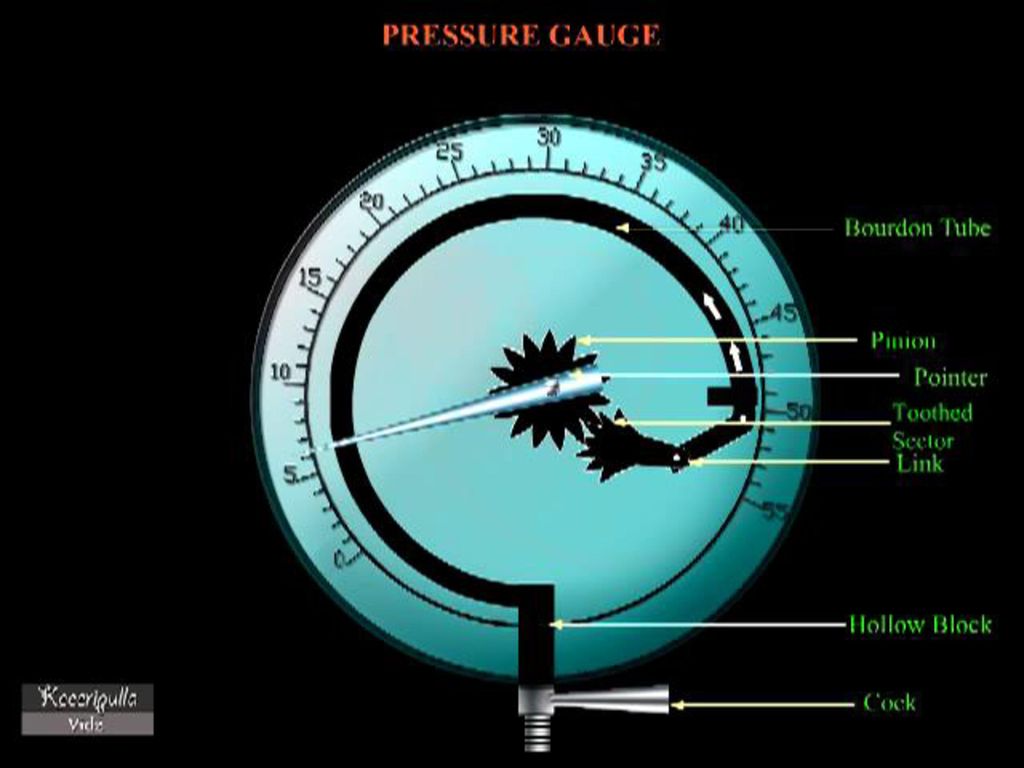
Pressure gauge The function of a pressure gauge is to measure the pressure exerted inside the vessels. It is usually constructed to indicate up to double the maximum working pressure. Its dial is graduated to read pressure in kgf/cm2 gauge. There are two type of pressure gauges, they are Bourdon tube type pressure gauge and Diaphragm tube type pressure gauge

94
Manhole and mud box Manhole provides opening for cleaning, inspection and maintenance purpose. Mud box is a collection chamber (as shown in Babcock and Wilcox boiler) for collecting the Mud.
 for collecting the Mud.")
95
Accessories of high pressure boiler
There are auxiliary plants required for steam boiler for their proper operation & for increase of their efficiency. The various accessories are 1. Feed pump: The feed pump is a pump which is used to deliver feed water to the boiler . It is desirable that the quantity of water supplied should be at least equal to that evaporated and supplied to the engine. Two type of pumps which are commonly used as feed pump are Reciprocating pump and Rotary pump.

98
2. Injector: The function of an injector is to feed water in to the boiler.
It is commonly employed for vertical and locomotive boiler and does not find its applications in large capacity high pressure boiler.

99
An injector, ejector, steam ejector, steam injector, eductor-jet pump or thermocompressor is a type of pump that uses the Venturi effect of a converging-diverging nozzle to convert the pressure energy of a motive fluid to velocity energy which creates a low pressure zone that draws in and entrains a suction fluid

100
After passing through the throat of the injector, the mixed fluid expands and the velocity is reduced which results in recompressing the mixed fluids by converting velocity energy back into pressure energy. The motive fluid may be a liquid, steam or any other gas. The entrained suction fluid may be a gas, a liquid, a slurry, or a dust-laden gas stream.

101
The adjacent diagram depicts a typical modern ejector.
It consists of a motive fluid inlet nozzle and a converging-diverging outlet nozzle. Water, air, steam, or any other fluid at high pressure provides the motive force at the inlet

102
Fluid under high pressure is converted into a high-velocity jet at the throat of the convergent-divergent nozzle which creates a low pressure at that point. The low pressure draws the suction fluid into the convergent-divergent nozzle where it mixes with the motive fluid.

103
the pressure energy of the inlet motive fluid is converted to kinetic energy in the form of velocity head at the throat of the convergent-divergent nozzle. As the mixed fluid then expands in the divergent diffuser, the kinetic energy is converted back to pressure energy at the diffuser outlet in accordance with Bernoulli's principle

104
Accessories of high pressure boiler
3. Evaporator: Evaporator is used in high pressure boiler which is placed after the air in the way of flue gases water are tube. Hence evaporator is a unit which consumes the energy of flue gases in boiler. Its main function is to convert the water to steam add much to the boiler efficiency.

106
Accessories of high pressure boiler
4. Economiser: An economiser is a device in which the waste heat of the flue gases is utilized for heating the feed water. Economiser is very important part of the boiler, with the help the economiser the efficiency of the boiler increased and the evaporative capacity of the boiler is increased. Economiser are of two type Independent type and Integral type. Video of economiser

108
Accessories of high pressure boiler
5. Super heater: The function of a super heater is to increase the temperature of the steam above its saturation point. Whatever type of boiler is used, steam will leave the water at its surface and pass into the steam space. Steam formed above the water surface in a shell boiler is always saturated and cannot become superheated in the boiler shell, as it is constantly in contact with the water surface.

109
If superheated steam is required, the saturated steam must pass through a super heater.
This is simply a heat exchanger where additional heat is added to the saturated steam. In water-tube boilers, the super heater may be an additional pendant suspended in the furnace area where the hot gases will provide the degree of superheat required (see Figure 3.4.4).
.")
110
Fig. 3.4.4 A water tube boiler with a super heater

112
Super heater

113
Accessories of high pressure boiler
6. Air-pre heater: The function of air pre heater is to increase the temperature of air before is enters the furnace. It is generally placed after the economiser. So that flue gases pass through the economiser and then to air preheat. Usually, there are three types of pre-heater are Tubular type, Plate type and Regenerative type.

115
Air pre heater Stationary-plate regenerative air preheater
Instead the air ducts in the preheater are rotated so as to alternatively expose sections of the heating plate elements to the upflowing cool air.[1][2][3] As indicated in the adjacent drawing, there are rotating inlet air ducts at the bottom of the stationary plates similar to the rotating outlet air ducts at the top of the stationary plates.

117
Tubular type A bundle of vertical tubes through which the flue gas flows downward (see adjacent diagram) and exchanges heat with ambient air flowing horizontally across the exterior of the tubes. . Baffles are usually provided so that the air flows across the tubes a number of times. For example, as shown in the adjacent diagram, the air flow across the tubes three times and is referred to as 3-pass tubular air pre heater. The same as (1) above except that the flue gas flows upward rather than downward. A bundle of horizontal tubes through which the air flows and exchanges heat with the hot flue gas flowing downward across the tube bundle
 above except that the flue gas flows upward rather than downward. A bundle of horizontal tubes through which the air flows and exchanges heat with the hot flue gas flowing downward across the tube bundle.")
118
. In some designs, there may be three separate horizontal tube bundles one above the other.
The air enters the lower tube bundle from the right-hand side, exits on the left-hand side and then enters the middle tube bundle on the left-hand side and exits on the right-hand side. Finally, the air enters the upper tube bundle on the right-hand side and exits on the left-hand side. In essence, such a design is similar to the 3-pass design of (1) above except that the air is in the tubes rather than outside the tubes.
 above except that the air is in the tubes rather than outside the tubes.")
119
Rankine cycle

120
Rankine cycle There are four processes in the Rankine cycle. These states are identified by numbers (in brown) in the above Ts diagram. Process 1-2: The working fluid is pumped from low to high pressure. As the fluid is a liquid at this stage the pump requires little input energy. Process 2-3: The high pressure liquid enters a boiler where it is heated at constant pressure by an external heat source to become a dry saturated vapors.

121
Process 3-4: The dry saturated vapor expands through a turbine, generating power. This decreases the temperature and pressure of the vapour, and some condensation may occur. Process 4-1: The wet vapour then enters a condenser where it is condensed at a constant pressure to become a saturated liquid. In an ideal Rankine cycle the pump and turbine would be isentropic, i.e., the pump and turbine would generate no entropy and hence maximize the net work output. Processes 1-2 and 3-4 would be represented by vertical lines on the T-S diagram and more closely resemble that of the Carnot cycle.

123
Draught This difference of pressure for to maintaining the constant flow of air and discharging the gases through the chimney to atmosphere is known as draught.

124
Draught A fuel-heated boiler must provide air to oxidize its fuel. Early boilers provided this stream of air, or draught, through the natural action of convection in a chimney connected to the exhaust of the combustion chamber. Since the heated flue gas is less dense than the ambient air surrounding the boiler, the flue gas rises in the chimney, pulling denser, fresh air into the combustion chamber. Most modern boilers depend on mechanical draught rather than natural draught. This is because natural draught is subject to outside air conditions and temperature of flue gases leaving the furnace, as well as the chimney height. All these factors make proper draught hard to attain and therefore make mechanical draught equipment much more reliable and economical. Types of draught can also be divided into induced draught, where exhaust gases are pulled out of the boiler; forced draught, where fresh air is pushed into the boiler; and balanced draught, where both effects are employed

125
Classification of draught

126
Draught Natural draught through the use of a chimney is a type of induced draught; mechanical draught can be induced, forced or balanced. There are two types of mechanical induced draught. The first is through use of a steam jet. The steam jet oriented in the direction of flue gas flow induces flue gasses into the stack and allows for a greater flue gas velocity increasing the overall draught in the furnace. This method was common on steam driven locomotives which could not have tall chimneys. The second method is by simply using an induced draught fan (ID fan) which removes flue gases from the furnace and forces the exhaust gas up the stack. Almost all induced draught furnaces operate with a slightly negative pressure. Mechanical forced draught is provided by means of a fan forcing air into the combustion chamber. Air is often passed through an air heater; which, as the name suggests, heats the air going into the furnace in order to increase the overall efficiency of the boiler. Dampers are used to control the quantity of air admitted to the furnace. Forced draught furnaces usually have a positive pressure.
 which removes flue gases from the furnace and forces the exhaust gas up the stack. Almost all induced draught furnaces operate with a slightly negative pressure. Mechanical forced draught is provided by means of a fan forcing air into the combustion chamber. Air is often passed through an air heater; which, as the name suggests, heats the air going into the furnace in order to increase the overall efficiency of the boiler. Dampers are used to control the quantity of air admitted to the furnace. Forced draught furnaces usually have a positive pressure.")
127
Draught Balanced draught is obtained through use of both induced and forced draught. This is more common with larger boilers where the flue gases have to travel a long distance through many boiler passes. The induced draught fan works in conjunction with the forced draught fan allowing the furnace pressure to be maintained slightly below atmospheric. Natural draft: When air or flue gases flow due to the difference in density of the hot flue gases and cooler ambient gases. The difference in density creates a pressure differential that moves the hotter flue gases into the cooler surroundings.[

129
ADVANTAGES : (1) It does not require any external power for producing the draught. (2) The capital investment is less. The maintenance cost is nil as there is no mechanical part. (3) Chimney keeps the flue gases at a high place in the atmosphere which prevents the contamination of atmosphere. (4) It has long life.
 The capital investment is less. The maintenance cost is nil as there is no mechanical part. (3) Chimney keeps the flue gases at a high place in the atmosphere which prevents the contamination of atmosphere. (4) It has long life.")
130
Forced draught In a forced draught system, a blower is installed near the base of the boiler. This draught system is known as positive draught system or forced draught system because the pressure of air throughout the system is above atmospheric pressure and air is forced to flow through the system. The arrangement of the system is shown in figure. A stack or chimney is also used in this system as shown in figure but it is not much significant for producing draught.

131
Forced draught

132
induced draught In this system, the blower is located near the base of the chimney instead of near the grate. The air is sucked in the system by reducing the pressure through the system below atmosphere. The action of the induced draught is similar to the action of the chimney. The draught produced is independent of the temperature of the hot gases therefore the gases may be discharged as cold as possible after recovering as much heat as possible in air pre-heater and economizer.

133
induced draught

134
induced draught This draught is used generally when economizer and air pre –heater are incorporated in the system. The fan should be located at such a place that the temperature of the gas handled by the fan is lowest. The chimney is also used in this system and its function is similar as mentioned in forced draught but total draught produced in induced draught system is the sum of the draughts produced by the fan and chimney. The arrangement of the system is shown in Figure.

135
Balanced draught The balanced draught is a combination of forced and induced draught. If the forced draught is used alone, then the furnace cannot be opened either for firing or inspection because the high pressure air inside the furnace will try to blow out suddenly and there is every chance of blowing out the fire completely and furnace stops.

136
Balanced draught If the induced draught is used alone, then also furnace cannot be opened either for firing or inspection because the cold air will try to rush into the furnace as the pressure inside the furnace is below atmospheric pressure. To overcome both the difficulties mentioned above either using forced draught or induced draught alone, a balanced draught is always preferred.

137
Balanced draught

138
comparision

139
Vapour process Constant pressure process
The generation of steam in boiler is an example of constant pressure process. In this process, the pressure of steam before and after the process is constant. We have already discussed heating of wet steam is done at constant pressure in order to convert it in to dry saturated steam. We also know that the superheating is done at a constant pressure.

142
Constant volume process
The heating or cooling of the steam in a closed vessel is an example of constant volume process. In this process, the volume (mass)of the steam before and after the process is constant. It may be noted that, in this process, no work is done.
of the steam before and after the process is constant. It may be noted that, in this process, no work is done.")
Similar presentations


![An Introduction To Marine Steam Propulsion Plant [Source: US Navy]](/2/754532/big_thumb.jpg "An Introduction To Marine Steam Propulsion Plant [Source: US Navy]>")


![[Asst.Prof. Mechanicl Engg. Dept.] [Electrical Engineering Department]](/7/1638279/big_thumb.jpg "[Asst.Prof. Mechanicl Engg. Dept.] [Electrical Engineering Department]>")


