Download presentation
Presentation is loading. Please wait.

1
Design a protection System of 220/33kV Grid Station United Arab Emirates University College of Engineering Saif Mohammed AL Aryani 200304349 Ahmed Soruor AL Shamisi 200304148 Mohammed AL Manei 200204241 Madyan Ahmed Assirri 200337000 Project Advisor: Dr. Ahmed Gaouda Examination Committee: Dr. Muftah El-Naas Dr. Imad Barhumi Dr. Hassan Nikkhajoei Graduation Project Code: EEMI-9

2
Introduction Protection System Single Line Diagram of Ramah Grid Busbar Protection Transformer Protection Distance Protection Implementation Conclusion & Recommendations OUTLINE

3
The graduation Project of our group is proposed from TRANSCO to UAE University. Transco Company is building now new Grid Substation in RAMAH to provide the enough power to that area. Introduction

4
Substation is the place where the power is stepped up or down. Substation contains: Feeder Transformer Busbar Bus coupler. Other Protection equipment Ramah Grid Substation power is stepped down by transformers from 220 KV to 33 KV. Introduction

5
Design a complete Protection System of 220 KV / 33KV Grid Station using ADWEA standard. Comparing the design results with existing systems and simulated results. Implantations of the simulated results. Introduction Objectives

6
Building a grid substation is very expensive. The protection of power system is the first thing that designer thinks about to safe the money and efforts. Any small mistake in the protection system can cause large damages and the designers will be blamed. The three goals of this protection are: Safety of Humans Safety of Equipment Safety of Supply Introduction Environmental Effects

7
Complete arrangement of protection equipments and other devices. Protection Equipments: – Current & Voltage Transformers ( CT & VT ). – Circuit Breaker (CB) – Relay Protection System
. – Circuit Breaker (CB) – Relay Protection System.")
8
Relays are like human brain A device that measures the (Current or voltage) of the system.. Protection System Relay

9
CT steps down the current to small value to be Suitable to the relay. Protection System CT

10
A switch like a (fuse) that used to interrupt the current flow. It opens on Relay Command. Protection System Circuit Breaker

11
Reasons for Zones: Amount of power carried Physical Structure. Function. Protection System Protection Zones

12
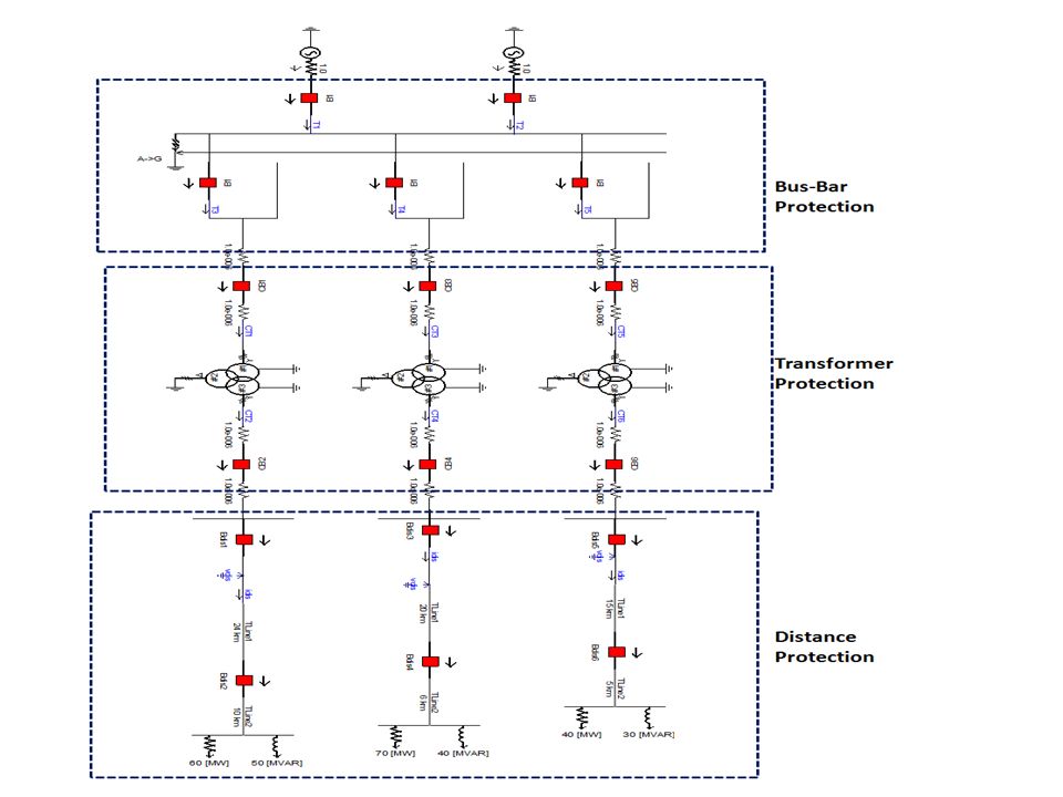
Single Line Diagram of RAMAH Grid

14
Incoming2Incoming1Outgiong1Outgiong2Bus coupler The busbar is a bar of copper or aluminum built in switchgear Bus-Bar Protection Single Line Diagram

15
In Fault Condition All Circuit Breaker will open Bus-Bar Protection

16
Bus-Bar Protection Simulated System in Normal Condition

17
Bus-Bar Protection Simulated System in Fault Condition

18
Incoming Current Outgoing Current Differential Current Tripping CBs Bus-Bar Protection Logics of Busbar Protection

19
Fault Starts after 1 s CBs opens after 0.1 s from fault Bus-Bar Protection Logics of Busbar Protection

20
Simulation Bus-Bar Protection

21
The electrical protection of the Transformer comprises of the following: Differential Current Protection. REF (Restricted Earth Fault). AVR (Automatic Voltage Regulator). Over current protection. Transformer Protection
. AVR (Automatic Voltage Regulator). Over current protection. Transformer Protection.")
22
Id = I1 – I2 ≠ 0 Transformer Protection Differential Current Protection

23
Transformer zone Transformer Protection Simulated System

24
Transformer Protection Logics of Differential Protection

25
In the event of failure or non- availability of the primary protection some other means of ensuring that the fault is isolated must be provided. These secondary systems are referred to as ‘back-up protection. Back-up protection Back- Up protection Transformer Protection Over Current Protection

26
Back- Up protection B1 Transformer Protection Logics of Transformer Protection

27
Transformer Protection System in Normal Condition

28
Transformer Protection System in differential fault condition

30
0.4 s Transformer Protection System in over current fault condition

31
Simulation Transformer Protection

32
Distance protection is used mainly for overhead lines protection. The main function of distance relays is to make high and fast protection system for the overhead lines. Distance Protection

33
Distance Protection Single Line Diagram of outgoing OHLs

34
Distance =30 Km Zone1 covers 80% (24 km) Zone2 covers 100% (30 km) Distance Protection RAMAH –ALANJAH Overhead Line
 Zone2 covers 100% (30 km) Distance Protection RAMAH –ALANJAH Overhead Line")
35
Distance Protection is applied to this line It is divided in two zones: – Zone-1 Covers 80 % of the Line (24 Km) – Zone-2 covers 100 % of the Line (30 Km) Distance Protection
 – Zone-2 covers 100 % of the Line (30 Km) Distance Protection")
36
The distance is depending on the impedance of the line. The voltage is calculated through VT. The Current is calculated through CT. Distance Protection

37
If fault happens in A: CB1 will operate after time t1 If fault happens in B: CB2 will operate. if it is not operated. CB1 will operate after time t1+0.3s If fault happens in C: CB1 and CB2 will not operate AB c CB1 CB2 Distance Protection

38
The impedance of the Line is : The calculated impedance by Relay: Z < 80 % Z line Fault happens in zone-1 80% Z line < Z < Z line Fault happens in Zone-2 Z> Z line No Fault happens in Line Distance Protection

39
If calculated impedance in Zone-1: Relay will trip after t1 If calculated impedance in Zone-2: Relay will trip after t1 + 0.3 s If calculated impedance outside zones: Relay will block Distance Protection

40
Distance Protection Simulated System in Normal Condition

41
Distance Protection Fault occurs in Zone-1

43
Distance Protection Fault occurs in Zone-1 & CB2 doesn’t operate

44
Voltage Magnitude Phase Voltages and phases for sequences Frequency Scanner Sequence Filter Distance Protection Logics of Distance Protection

45
Current and phases for sequences Current Magnitude Phase Frequency Scanner Sequence Filter Distance Protection Logics of Distance Protection

46
V & I parameters R-X Plane Define the Zone of fault Trip CB1 Trip CB2 Distance Protection Logics of Distance Protection

47
CB opens after 0.3 s from fault Fault Starts after 1 s Distance Protection

48
Simulation Distance Protection

49
Implementation

50
In this GP; there were long steps of calculations and simulation using PSCAD program which allows the designer to simulate the large values of power in details. After doing all these steps; the simulated results will be sent to Transco Company to be as a real setting for the protection system.. Conclusion

51
Thanks for Good Listening Any Questions?

Similar presentations


 80% Are consequential Things to.>")

, 6-9 June 2011 Louise Jakobsen, Danish Energy Association – Denmark – Session 3 – Paper 0811 Louise Jakobsen, Danish Energy Association.>")
