Download presentation
Presentation is loading. Please wait.

1
Control Systems: Circuitry Electricity for Refrigeration, Heating and Air Conditioning 7th Edition Chapter 16 Control Systems: Circuitry and Troubleshooting

2
Control Systems: Circuitry and Troubleshooting Upon completion of this chapter the student will be able to: Understand basic control circuits, including compressor, evaporator fan motor, condenser fan motor, and safety control circuits Understand the basic circuitry of control systems used on light commercial and commercial and Industrial applications Identify the method of control for industrial systems Understand the control circuitry used in residential applications

3
Key Terms Capacity Control Electric Control System Electronic Control System Head Pressure Interlock Pneumatic Control System Pump-Down System Water Chiller

4
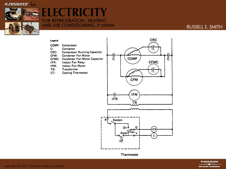
Basic Control Circuits All control systems have certain circuits and components in common. Most air-conditioning systems have a contactor to start and stop the com pressor. The compressor is the largest electric load in an air-conditioning system. The control of the condenser fan motor is common on many systems. Circuits controlling the evaporator fan motor are common because of the use of an evaporator fan relay, but on heating systems different methods are used.

5
Compressor Control Circuits The first basic circuit of almost any residential or small commercial air- conditioning control system is the device that starts and stops the compressor. On a low-voltage control system, the thermostat opens or closes to energize or dc-energize the contactor, which starts or stops the compressor. The condenser fan motor is usually connected directly to the contactor to ensure that it is operating whenever the compressor is in operation

6
Evaporator Fan Motor Control Circuits The evaporator fan motor operates from a relay controlled by the thermostat. If the thermostat fan switch is set on the “on” position, the indoor fan relay will be energized by the cooling function of the thermostat. On heating installations, other controls are needed to start the fan.

7
Condenser Fan Motor Control Circuit Most condenser fan motors on residential air-conditioning systems are controlled by the contactor because of the simplicity and the economy of using one control. Some condenser fan motors are cycled on and off through an outdoor thermostat set at a temperature that will maintain a constant head pressure. This allows better system efficiency.

8
Condenser Fan Motor Control Circuits Most condenser fan motors on residential air-conditioning systems are controlled by the contactor because of the simplicity and the economy of using one control. Some condenser fan motors are cycled on and off through an outdoor thermostat set at a temperature that will maintain a constant head pressure. This allows better system efficiency.

9
Safety Control Circuits Most safety controls used in residential and small commercial systems are connected in series with the contactor coil. The only exception is the internal thermostat in a compressor, which breaks the power wires inside the compressor. Any other safety devices used in the control system, such as a high- pressure switch or a low-pressure switch, are connected in series with the contactor coil. The series connection ensures that in the case of an unsafe condition, the compressor will be dc-energized.

10
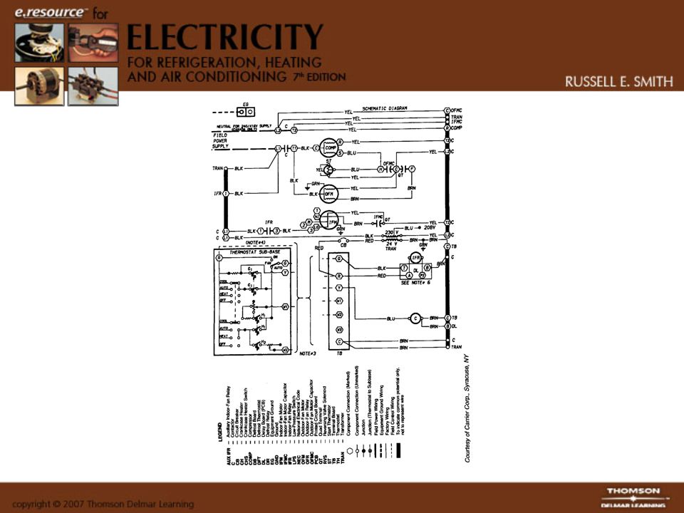
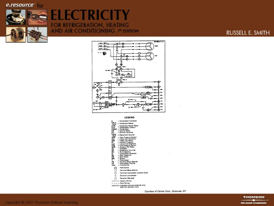
Total Control System of Residential Units The thermostat is a switching point of the low-voltage supply to the necessary components. From the schematic it can be seen that the indoor fan motor can operate continuously or cycle with the cooling thermostat, depending on the position of the fan function switch. The remainder of the thermostat operates the heating or cooling or both. The cooling thermostat will close or open to the correct temperature, as well as control the heating by the heating thermostat. The contactor is energized by the cooling thermostat until the temperature is decreased to the desired range. The evaporator fan motor is energized on the cooling cycle by the indoor fan relay and on the heating cycle by a fan switch contained in the furnace. This control system is commonly used on residential and small commercial air- conditioning and heating systems.

11
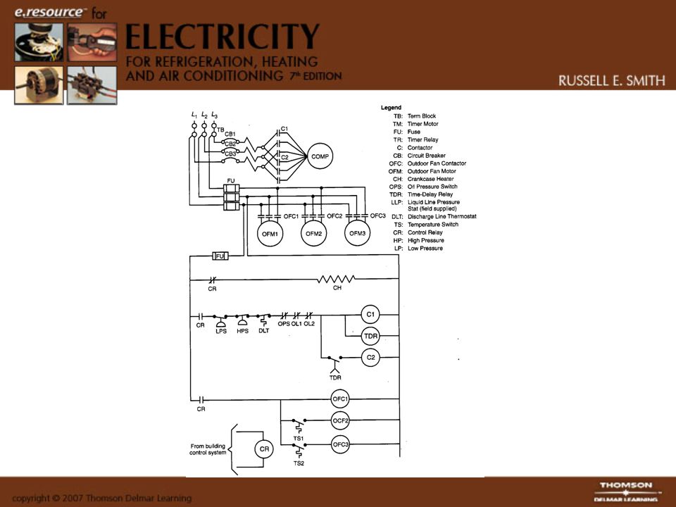
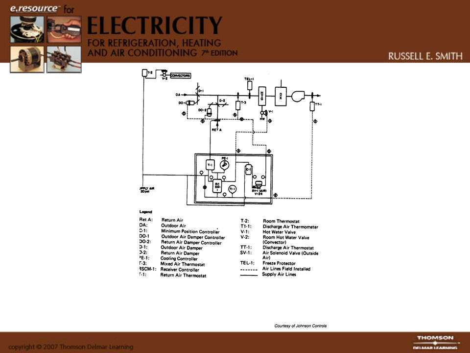
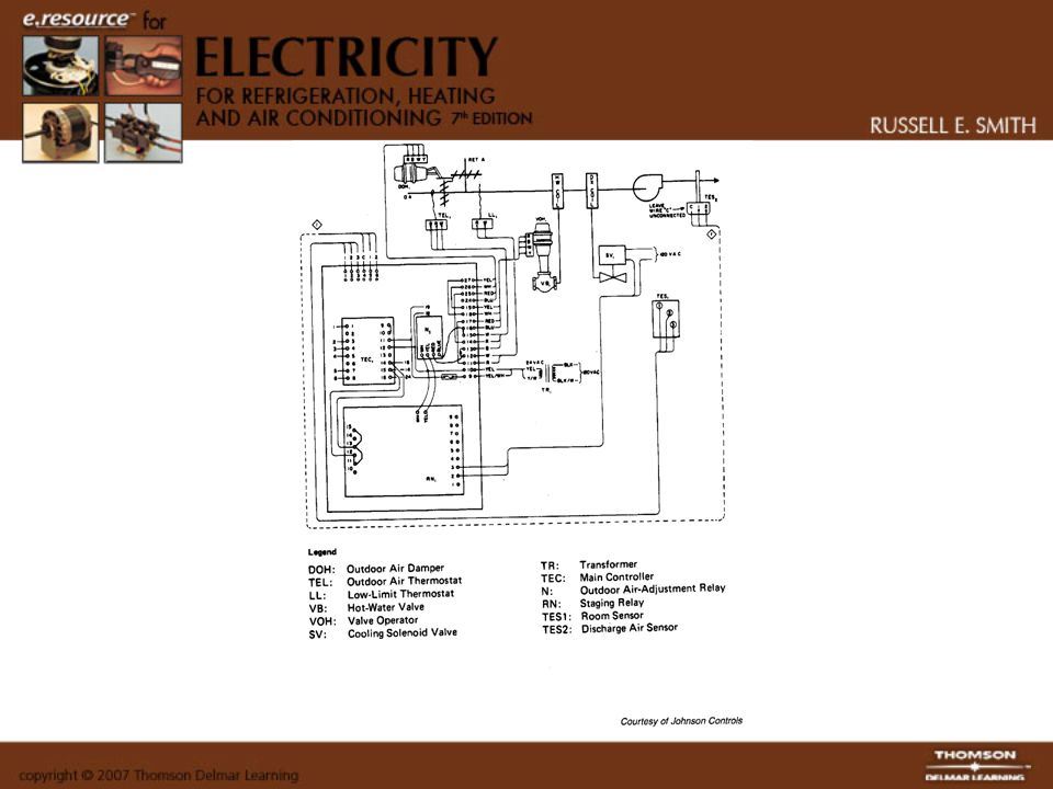
Advanced Control Systems All types and designs of control systems are used in commercial and industrial air-conditioning, heating, or refrigeration systems. The control systems used in equipment from 7.5 to 100 tons cannot afford to be as simple and use as few components as the smaller systems. Most large systems use some method of capacity control because of the variations in the load in the conditioned areas. When capacity control is used on these larger air-conditioning systems, it usually involves a more complex control system. Also, most large air-conditioning and heating systems have several important control circuits that prevent short-cycling and operation of the equipment under conditions that would cause damage.

12
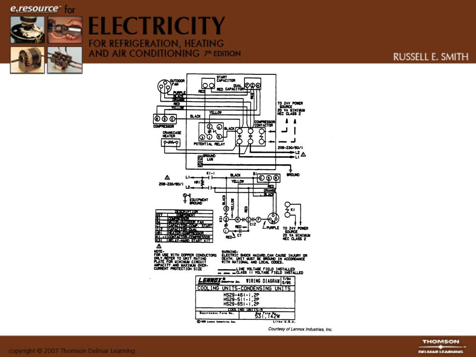
Compressor Motor Controls There are two methods of energizing the compressor on the large systems, part winding and across the line. The contactor or magnetic starter is used to energize the compressor on all systems. An across-the-line type of motor starting requires only a single contactor. However, a part winding motor would require two contactors along with a time-delay relay. The part winding motor is used to allow the compressor to start more easily, with less wear and tear. The part winding motor is actually broken down into two separate windings, with the first winding energized 1.5 to 3 seconds before the second winding is energized.

13
Water Chiller Control Systems Water chillers are refrigeration systems that cool the water pumped into other parts of the system to maintain the desired condition of a specific area. The control on a water chiller will usually come from the chilled water temperature, which will relate the information back to the refrigeration control system. This type of control can also include a pump-down system.

14
Evaporator Fan Motor Controls Fan motors are generally designed to operate at all time in the larger systems and are cut on and off by a clock or a system switch. These fan motors are interlocked into the control system of the condensing unit to ensure the operation of the fan motor whenever the condensing unit is operating. The smaller commercial air-conditioning and heating units usually cut off their fan motors on the “off’ cycle of the equipment.

15
Condenser Fan Motor Controls The condenser fan motor used on most commercial and industrial air- conditioning units is usually designed to maintain a constant head pressure by operating a certain number of condenser fans when the outside tempera ture drops below 750F. This is accomplished by using thermostats to operate the condenser fan motors at certain outdoor temperatures or by using reverse-acting high- pressure switches to cycle the fans.

16
Water-Cooled Condenser Interlocks Water-cooled condensing units require an interlock in the condensing unit control circuit. The interlock ensures that the air-conditioning unit does not start unless the cooling tower pump and the cooling tower fan motor are operating.

17
Water Chiller Interlocks Water chillers require an interlock in the chiller control circuit to ensure that the chilled water pump is operating before the water chiller refrigeration unit will operate. This interlock ensures that the water chiller will not accidentally freeze the water in the evaporator, causing a rupture of the evaporator.

Similar presentations


>")


 UNIT 40 TYPICAL OPERATING CONDITIONS>")


