Download presentation
Presentation is loading. Please wait.

1
FLIGHT CONTROLS AND HYDRAULICS

2
FLIGHT CONTROLS The flight control systems are mechanical linkages, actuated by conventional controls, and are used to control flight attitude and direction. The cyclic control and collective control systems have hydraulic boost. A synchronized elevator is linked into the fore and aft control system at the cyclic torque tube.

3
The controls are routed beneath the cockpit seats, aft to the center of the helicopter, and up through the control column to the cabin roof. Access doors located on the aft side of the control column and seat panels are provided for inspections of control components, and for maintenance accessibility. Cyclic and collective controls are routed to the main rotor blades through the swashplate. The directional controls are routed through the tail boom to the tail rotor.

4
CYCLIC CONTROL LINKAGE

5
FRICTIONADJUSTMENT

6
COLLECTIVECONTROLLINKAGE

7
COLLECTIVE FRICTION ADJUSTMENT

8
ANTI-TORQUE CONTROL LINKAGE

9
Mixing Lever

10
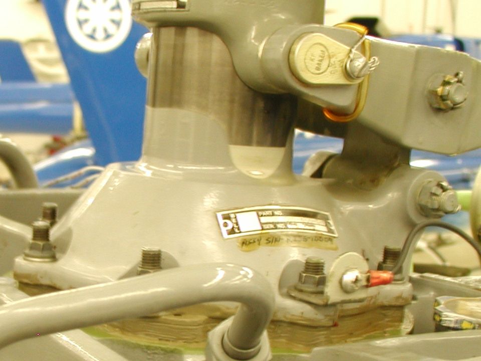
TRANSMISSION BELL CRANKS

11
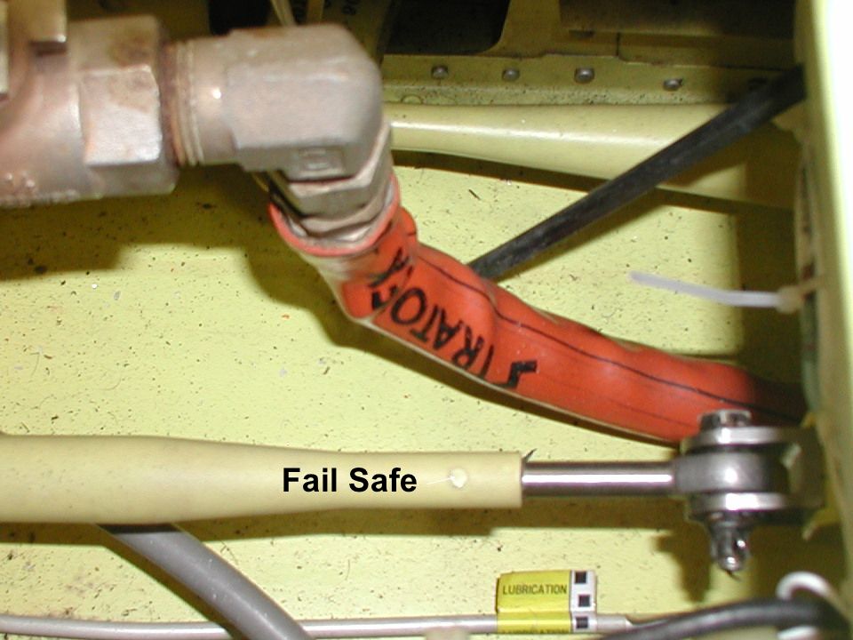
Fail Safe

13
Pedal Weight

16
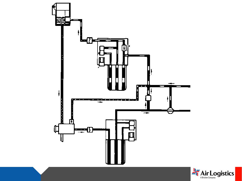
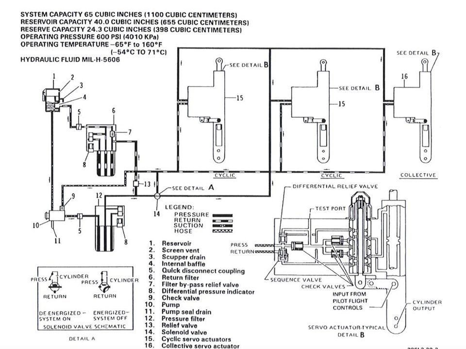
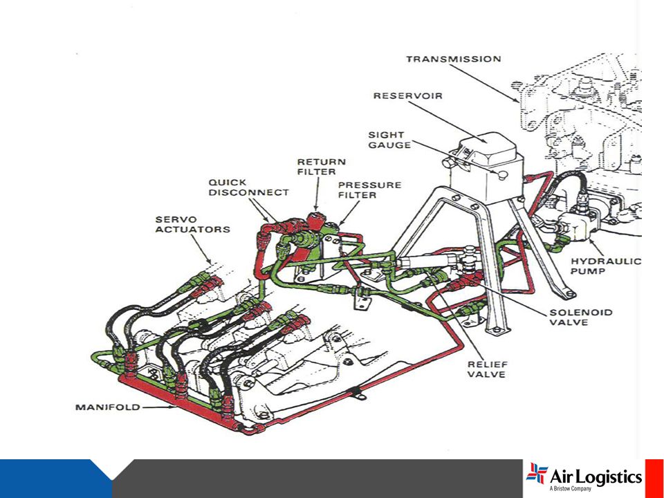
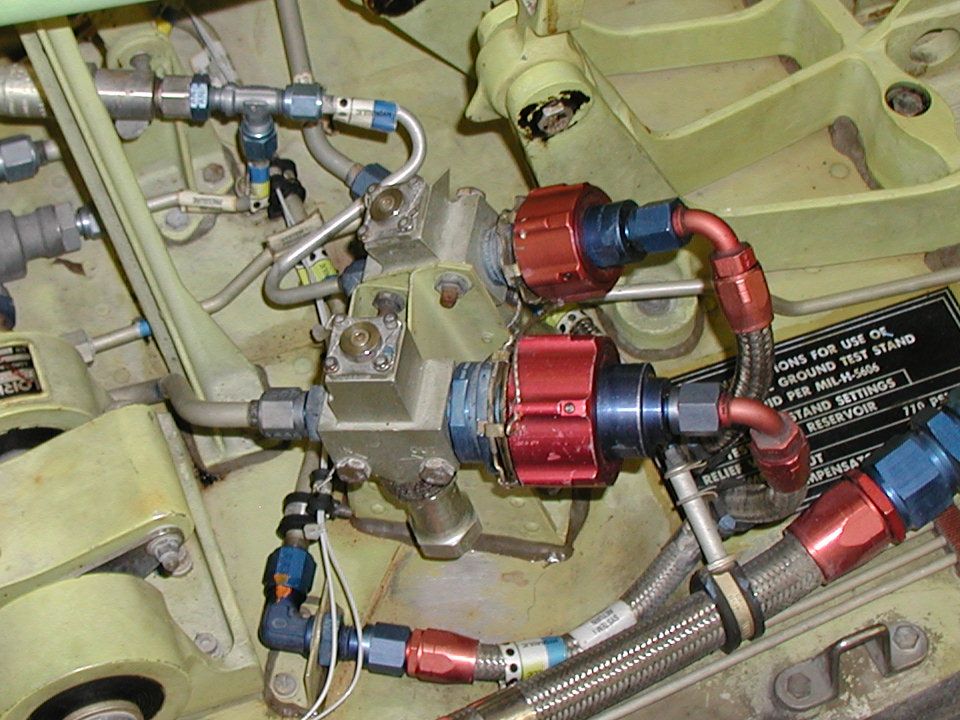
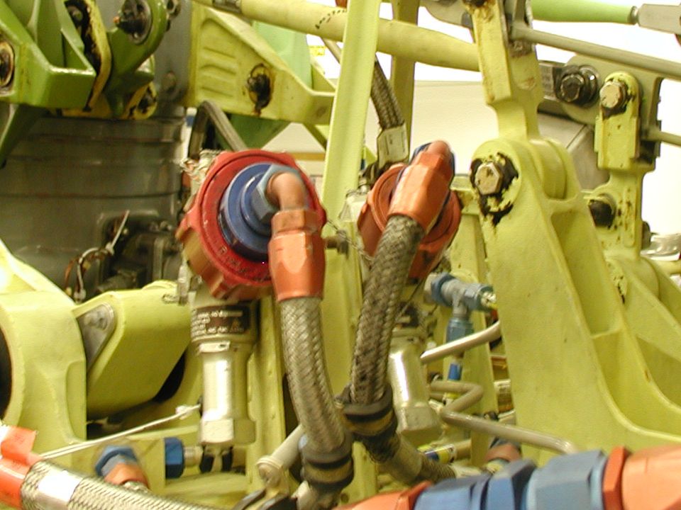
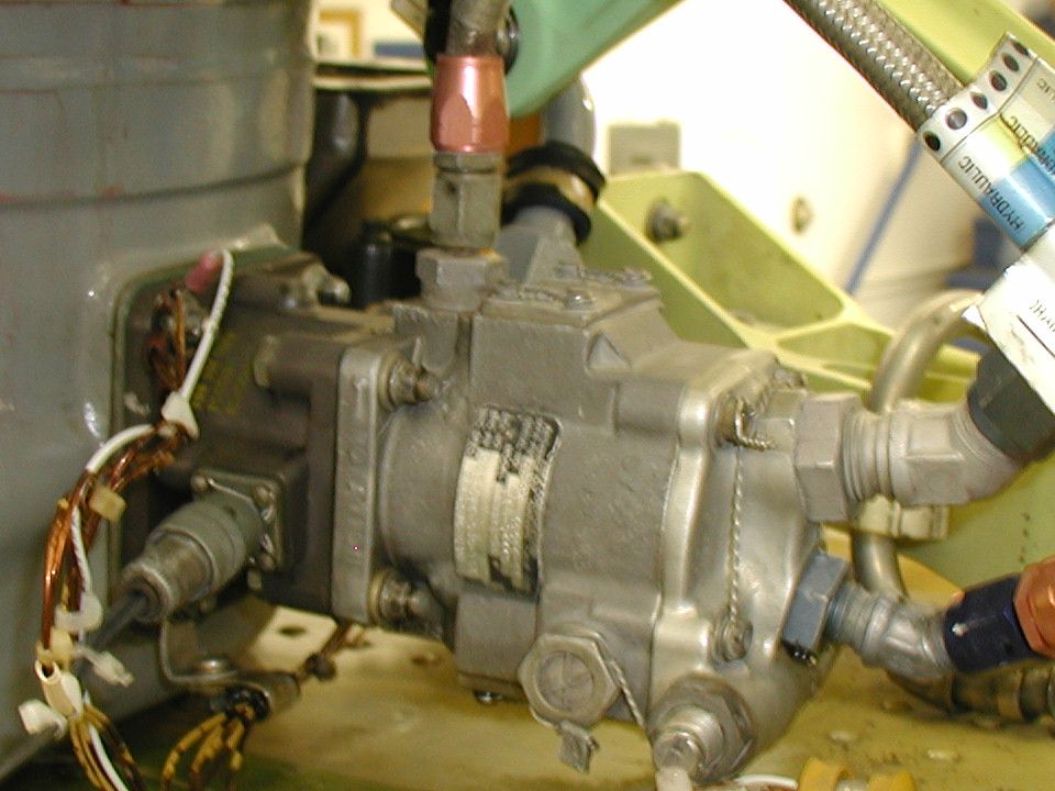
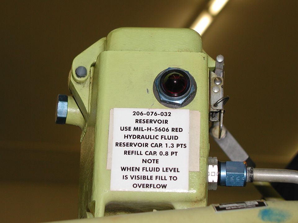
HYDRAULIC SYSTEM The transmission driven hydraulic pump provides for fully boosted flight controls being available during autorotative flight. The pump is mounted on and driven through the rotor tachometer generator. The pump is a variable delivery type and provides system pressure of 600 +/- 25 psi. The hydraulic reservoir is made from magnesium alloy. The reservoir is mounted on a brace and support forward of the transmission, and above the hydraulic pump assembly.

17
Fluid level may be observed through a transparent plastic sight glass in the left side of the reservoir. Two filter assemblies are installed in the system; one in the pressure supply line, and on in the return line. The return line filter assembly incorporates a bypass valve. A pressure relief valve is installed between the pressure line and the return line to protect the system from excessive pressure.

18
If the system exceeds the normal pressure range, the relief valve will bypass the high pressure back to the reservoir. When the pressure reaches 670-770 psi. The hydraulic system "on and off" solenoid valve, mounted on the cabin roof is a "fail safe" type, spring loaded to "normally open" position. The only method to turn the system off is the application of electrical power through the "HYDRAULIC SYSTEM" switch on the instrument panel.

19
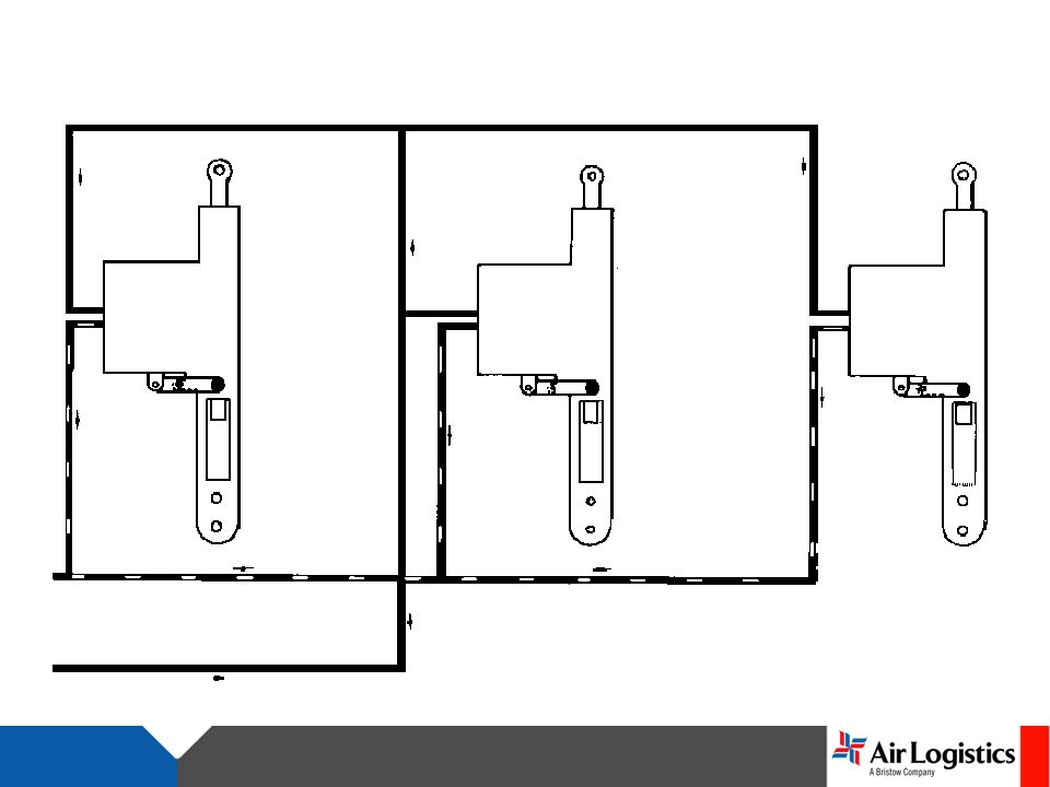
HYDRAULICSYSTEM

Similar presentations