Download presentation
Presentation is loading. Please wait.

1
ECS and MINISTAB System Capt Johnson

4
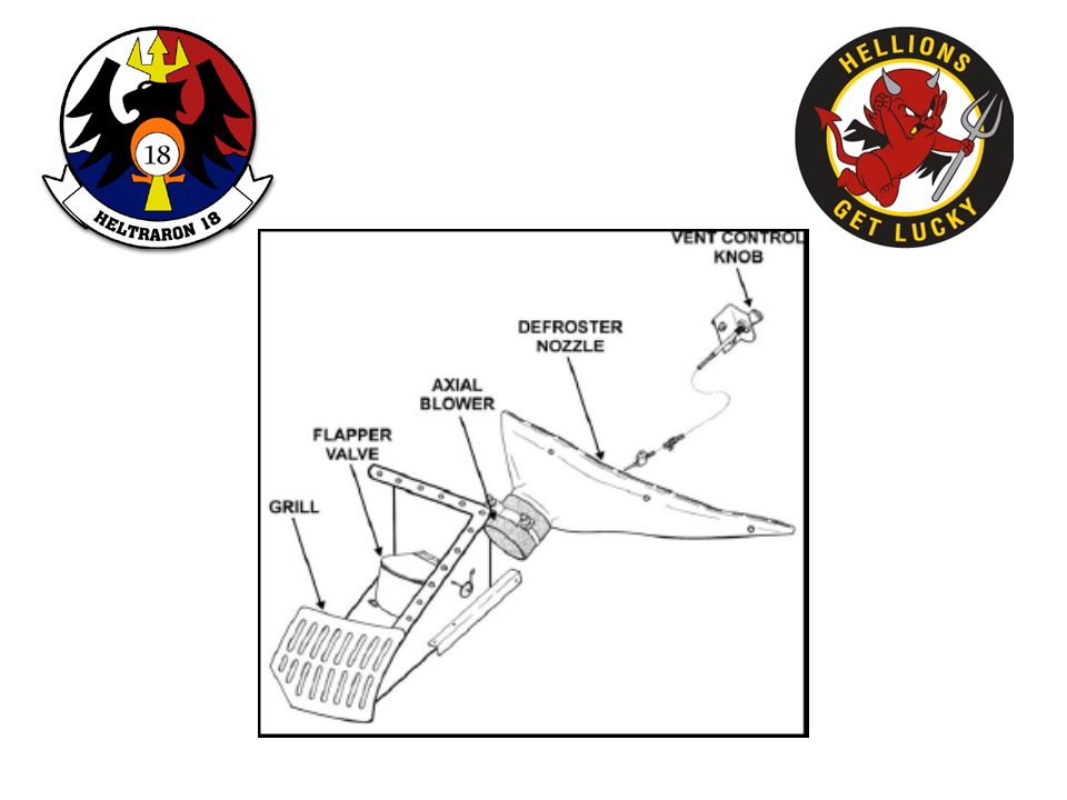
Two vent controls are mechanically connected to flapper valves, which lock in different positions to vary the amount of air entering the cabin along with diverting air to the defog system when the vent control knobs are pulled out. Two electrically driven axial flow blowers are installed in the inlet end of the defroster nozzles which maintain a continuous flow of air, depending on the cockpit setting. This defog system is primarily used for ventilation and defogging during ground ops.

5
Although not required, airflow will be increased when both vent control knobs are pulled full out. The defog system works best when operated in conjunction with the a/c or heater system. To operate : Turn the air conditioner or heat switch on; Turn the defog blower on; Select high or low fan speed and open the air conditioner or heater outlets. (when using defog in conjunction with a/c or heater, close the ram air vents)
.")
6
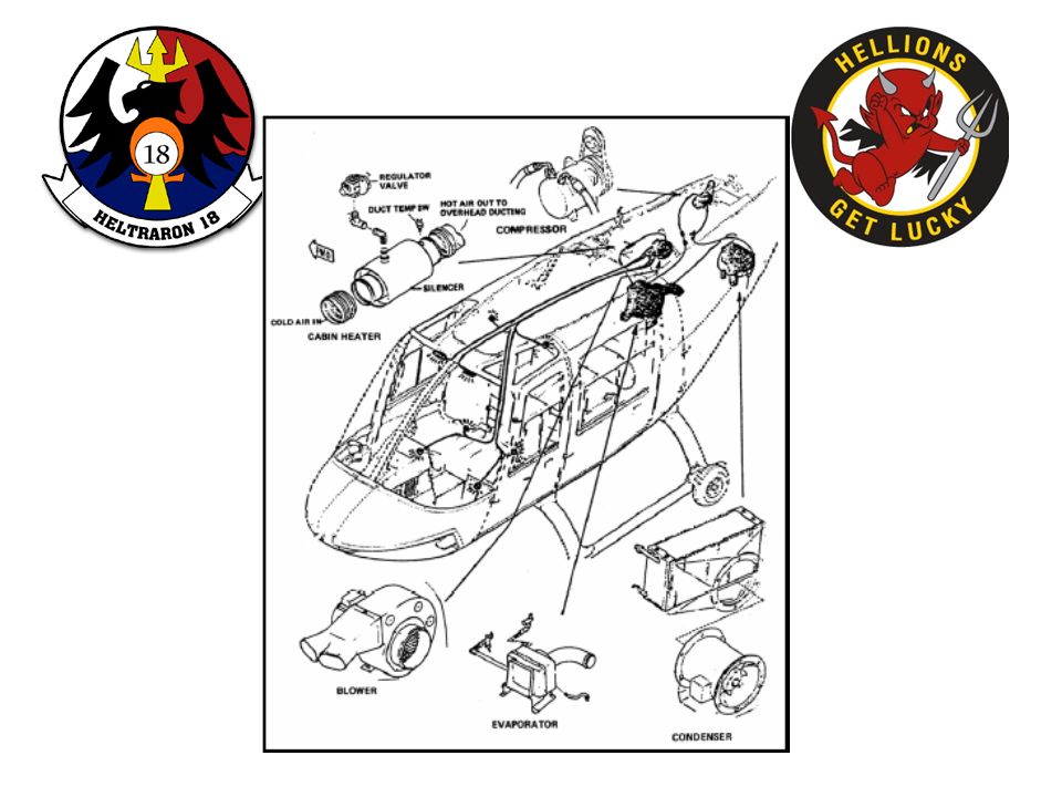
Vapor Cycle Air Conditioner

7
A/C system requires approximately ______ horsepower to operate. Five

10
The compressor is driven by a pulley and belt arrangement off of the tail rotor drive shaft. When the electrical circuit to the compressor is completed, an electrical clutch engages and the compressor begins to pump freon gas from the evaporator.

12
The compressor compresses the gas to a high pressure and temperature and then routes it to the condenser, where the pressurized freon gas flows through the condenser coils and condenses to a liquid when cooled by the condenser fan blowing air over the coils. The liquid freon is then stored under pressure in the receiver dryer located next to the evaporator. The receiver dryer stores the liquid freon for on- demand use of the evaporator.

13
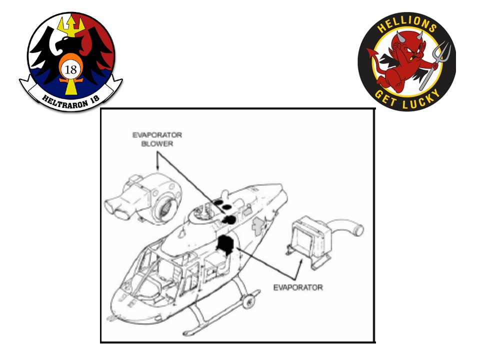
Flow of freon to the evaporator is controlled by two thermostatically controlled expansion valves. The expansion valves work on temperature and pressure. With the compressor operating, a low pressure is created from the evaporator to the compressor, and the expansion valves open, providing a means to meter the liquid through the evaporator at a rate so it will be a gas by the time it reaches the compressor.

14
As the liquid passes through the expansion valves and enters the low pressure evaporator, it reverts back to a gas (absorbing heat). During this processes while the gas is absorbing heat and cooling the evaporator coils, the evaporator fan is pulling cabin air through the coils and returning cool air back to the cabin.

15
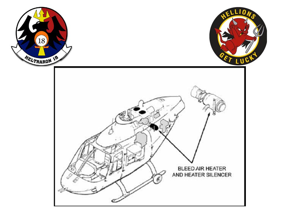
Bleed Air Heater Inlet side of the heater system is connected to the ventilation ducting coming from the evaporator and the outlet is connected by ventilation ducting to the evaporator blower. The control valve on the overhead console determines the amount of bleed air mixing with cabin air by governing the airflow to the regulator valve. With the regulator valve open, a proportional amount of engine bleed air enters the heater silencer, which then mixes with cabin air and is circulated by the evaporator fan. A duct temp switch in the heater silencer monitors the air temp in the outlet side of the heater silencer.

17
Heater Malfunction Indications: DUCT TEMP HIGH caution light illuminated Procedures: 1. CABIN HEAT valve – OFF 2. AIR COND/FAN switch – FAN 3. HI/FAN/LO switch – HI If light extinguishes: 4. Continue flight If light does not extinguish: 5. Land as soon as practical

18
MINISTAB

19
The MINISTAB is a basic three-axis stabilization system with force trim and rate dampening in all three axes. Each axis includes a: Trim Damper Unit Computer Actuator The air data computer provides airspeed and altitude information to the system and the controller and actuator position indicator provide the pilot with system information. A Junction box works with all three axis

20
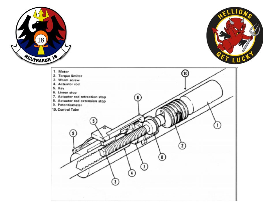
Electromechanical Actuator Installed in the top of the cyclic control tube with the output shaft connected directly to the hydraulic booster pilot valve input. The rudder actuator is installed in line with the tail rotor control tube. Signals from computers cause the actuator to move about a neutral point, with cyclic actuators moving simultaneously (opposite directions for roll input and in the same direction for pitch input).
..")
23
Trim Damper Unit TDU’s are multipurpose with force trim and damper sections. The force trim operates as a standard force gradient, providing artificial feel while maintaining the last control position. The damper serves to smooth pilot input into the AFCS. (Microswitch’s located in pitch and roll TDU)
.")
24
Control tube actuators Junction Box Roll computer / Pitch trim damper Pitch computer / Roll trim damper Yaw computer

25
Junction Box interconnects components of the system Roll computer and junction box are located under the pilot’s seat Pitch and Yaw computers are located under the copilot’s seat. All three axis computers are identical, containing a: rate gyro memory circuit (integrated rate) Integration Cutoff (ICO) circuit The rate gyro senses movement about its axis, with the computer detecting any deviation from the “attitude” stored in the memory circuit. The computer sends a correction signal to the actuator, which makes the appropriate control input.
 Integration Cutoff (ICO) circuit The rate gyro senses movement about its axis, with the computer detecting any deviation from the attitude stored in the memory circuit. The computer sends a correction signal to the actuator, which makes the appropriate control input..")
26
ICO occurs when:

27
To change to a new pitch attitude: move the cyclic fore or aft and a microswitch in the pitch TDU senses the movement and activates the pitch computer ICO. Once control movement stops, the computer waits for movement about its axis to stabilize below 1.5º per second…and 900 milliseconds later the ICO is secured again. This delay lets the aircraft settle down, then the computer maintains the new attitude. To accomplish new roll attitudes, equal signals are sent to both cyclic actuators, except one signal is reversed in polarity for roll input, left or right. Again, lateral cyclic movement causes ICO to occur and once the aircraft stabilizes, the roll computer maintains the new roll attitude.

28
For the yaw axis, the principle is the same. A rate gyro in the yaw computer senses changes about its axis and makes inputs to the tail rotor controls to hold the last heading set. The yaw system has the microswitches located in the pedal assemblies and not in the TDU. To change heading, move the pedals to the new setting. The microswitch will ICO the computer and once the computer detects the aircraft has settled down, it will maintain the new heading.

29
Depressing the altitude hold button on the controller will engage the air data computer and maintain the selected altitude. The air data computer contains an airspeed trip switch, which prevents the altitude hold function from working if airspeed is less than 40 kts. With airspeed above 40 kts, and altitude hold engaged, the altitude hold circuits of the air data computer will determine if the aircraft is above or below the desired altitude. Then an altitude error pitch signal that is proportional to the amount of error is sent to momentarily cause the pitch computer to go to ICO. Notice, altitude hold only affects the PITCH AXIS. Roll and yaw are not affected.

30
If you are low, pitch angle will change to raise the nose and as a result, airspeed will decrease. The air data computer will maintain altitude except that if the computer senses an altitude error signal greater than 150 feet, the air data computer will automatically disengage.

31
With the MINISTAB in operation the VNE is reduced to 122 kts at density altitudes of 3000 and below. The VNE for aircraft flying above 3000 feet density altitude will depend on gross weight and density altitude flown. Check your NATOPS for other restrictions.

Similar presentations


>")


>")


