Download presentation
Presentation is loading. Please wait.

2
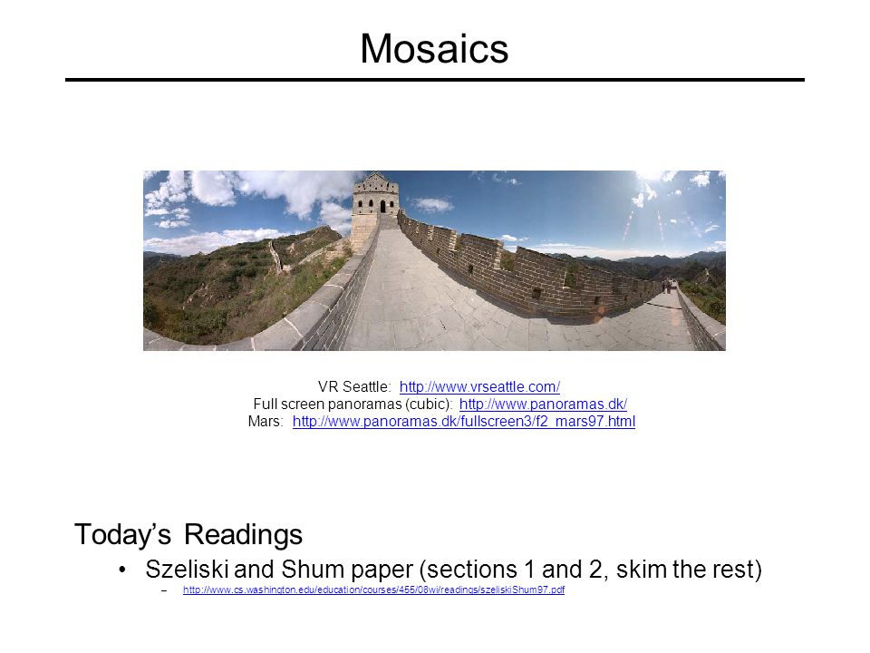
Mosaics Today’s Readings Szeliski and Shum paper (sections 1 and 2, skim the rest) –http://www.cs.washington.edu/education/courses/455/08wi/readings/szeliskiShum97.pdfhttp://www.cs.washington.edu/education/courses/455/08wi/readings/szeliskiShum97.pdf VR Seattle: http://www.vrseattle.com/http://www.vrseattle.com/ Full screen panoramas (cubic): http://www.panoramas.dk/http://www.panoramas.dk/ Mars: http://www.panoramas.dk/fullscreen3/f2_mars97.htmlhttp://www.panoramas.dk/fullscreen3/f2_mars97.html
 – VR Seattle: Full screen panoramas (cubic): Mars:")
3
Image Mosaics + + … += Goal Stitch together several images into a seamless composite

4
How to do it? Basic Procedure Take a sequence of images from the same position –Rotate the camera about its optical center Compute transformation between second image and first Shift the second image to overlap with the first Blend the two together to create a mosaic If there are more images, repeat

5
Project 2 1.Take pictures on a tripod (or handheld) 2.Warp to spherical coordinates 3.Extract features 4.Align neighboring pairs using RANSAC 5.Write out list of neighboring translations 6.Correct for drift 7.Read in warped images and blend them 8.Crop the result and import into a viewer Roughly based on Autostitch By Matthew Brown and David Lowe http://www.cs.ubc.ca/~mbrown/autostitch/autostitch.html
 2.Warp to spherical coordinates 3.Extract features 4.Align neighboring pairs using RANSAC 5.Write out list of neighboring translations 6.Correct for drift 7.Read in warped images and blend them 8.Crop the result and import into a viewer Roughly based on Autostitch By Matthew Brown and David Lowe")
6
Aligning images How to account for warping? Translations are not enough to align the images Photoshop demo

7
mosaic PP Image reprojection The mosaic has a natural interpretation in 3D The images are reprojected onto a common plane The mosaic is formed on this plane

8
Image reprojection Basic question How to relate two images from the same camera center? –how to map a pixel from PP1 to PP2 PP2 PP1 Answer Cast a ray through each pixel in PP1 Draw the pixel where that ray intersects PP2 Don’t need to know what’s in the scene!

9
Image reprojection Observation Rather than thinking of this as a 3D reprojection, think of it as a 2D image warp from one image to another

10
Homographies Perspective projection of a plane Lots of names for this: –homography, texture-map, colineation, planar projective map Modeled as a 2D warp using homogeneous coordinates Hpp’ To apply a homography H Compute p’ = Hp (regular matrix multiply) Convert p’ from homogeneous to image coordinates –divide by w (third) coordinate
 Convert p’ from homogeneous to image coordinates –divide by w (third) coordinate")
11
Image warping with homographies image plane in frontimage plane below black area where no pixel maps to

12
Panoramas What if you want a 360 field of view? mosaic Projection Sphere

13
Map 3D point (X,Y,Z) onto sphere Spherical projection X Y Z unit sphere unwrapped sphere Convert to spherical coordinates Spherical image Convert to spherical image coordinates –s defines size of the final image »often convenient to set s = camera focal length
 onto sphere Spherical projection X Y Z unit sphere unwrapped sphere Convert to spherical coordinates Spherical image Convert to spherical image coordinates –s defines size of the final image »often convenient to set s = camera focal length")
14
Spherical reprojection Y Z X side view top-down view to How to map sphere onto a flat image?

15
Spherical reprojection Y Z X side view top-down view to –Use image projection matrix! –or use the version of projection that properly accounts for radial distortion, as discussed in projection slides. This is what you’ll do for project 2. How to map sphere onto a flat image?

16
Correcting radial distortion from Helmut DerschHelmut Dersch

17
Modeling distortion To model lens distortion Use above projection operation instead of standard projection matrix multiplication Apply radial distortion Apply focal length translate image center Project to “normalized” image coordinates

18
f = 200 (pixels) Spherical reprojection Map image to spherical coordinates need to know the focal length inputf = 800f = 400
 Spherical reprojection Map image to spherical coordinates need to know the focal length inputf = 800f = 400")
19
Aligning spherical images Suppose we rotate the camera by about the vertical axis How does this change the spherical image?

20
Aligning spherical images Suppose we rotate the camera by about the vertical axis How does this change the spherical image? Translation by This means that we can align spherical images by translation

21
Spherical image stitching What if you don’t know the camera rotation? Solve for the camera rotations –Note that a pan (rotation) of the camera is a translation of the sphere! –Use feature matching to solve for translations of spherical-warped images
 of the camera is a translation of the sphere. –Use feature matching to solve for translations of spherical-warped images.")
22
Project 2 1.Take pictures on a tripod (or handheld) 2.Warp to spherical coordinates 3.Extract features 4.Align neighboring pairs using RANSAC 5.Write out list of neighboring translations 6.Correct for drift 7.Read in warped images and blend them 8.Crop the result and import into a viewer Roughly based on Autostitch By Matthew Brown and David Lowe http://www.cs.ubc.ca/~mbrown/autostitch/autostitch.html
 2.Warp to spherical coordinates 3.Extract features 4.Align neighboring pairs using RANSAC 5.Write out list of neighboring translations 6.Correct for drift 7.Read in warped images and blend them 8.Crop the result and import into a viewer Roughly based on Autostitch By Matthew Brown and David Lowe")
23
Feature detection summary Here’s what you do Compute the gradient at each point in the image Create the H matrix from the entries in the gradient Compute the eigenvalues. Find points with large response ( - > threshold) Choose those points where - is a local maximum as features
 Choose those points where - is a local maximum as features.")
24
The Harris operator - is a variant of the “Harris operator” for feature detection The trace is the sum of the diagonals, i.e., trace(H) = h 11 + h 22 Very similar to - but less expensive (no square root) Called the “Harris Corner Detector” or “Harris Operator” Lots of other detectors, this is one of the most popular
 = h 11 + h 22 Very similar to - but less expensive (no square root) Called the Harris Corner Detector or Harris Operator Lots of other detectors, this is one of the most popular")
25
The Harris operator Harris operator

26
Take 40x40 square window around detected feature Scale to 1/5 size (using prefiltering) Rotate to horizontal Sample 8x8 square window centered at feature Intensity normalize the window by subtracting the mean, dividing by the standard deviation in the window CSE 576: Computer Vision Multiscale Oriented PatcheS descriptor 8 pixels 40 pixels Adapted from slide by Matthew Brown
 Rotate to horizontal Sample 8x8 square window centered at feature Intensity normalize the window by subtracting the mean, dividing by the standard deviation in the window CSE 576: Computer Vision Multiscale Oriented PatcheS descriptor 8 pixels 40 pixels Adapted from slide by Matthew Brown")
27
Feature matching Given a feature in I 1, how to find the best match in I 2 ? 1.Define distance function that compares two descriptors 2.Test all the features in I 2, find the one with min distance

28
Feature distance How to define the difference between two features f 1, f 2 ? Simple approach is SSD(f 1, f 2 ) –sum of square differences between entries of the two descriptors –can give good scores to very ambiguous (bad) matches I1I1 I2I2 f1f1 f2f2
 –sum of square differences between entries of the two descriptors –can give good scores to very ambiguous (bad) matches I1I1 I2I2 f1f1 f2f2.")
29
Feature distance How to define the difference between two features f 1, f 2 ? Better approach: ratio distance = SSD(f 1, f 2 ) / SSD(f 1, f 2 ’) –f 2 is best SSD match to f 1 in I 2 –f 2 ’ is 2 nd best SSD match to f 1 in I 2 –gives small values for ambiguous matches I1I1 I2I2 f1f1 f2f2 f2'f2'
 / SSD(f 1, f 2 ’) –f 2 is best SSD match to f 1 in I 2 –f 2 ’ is 2 nd best SSD match to f 1 in I 2 –gives small values for ambiguous matches I1I1 I2I2 f1f1 f2f2 f2 f2 .")
30
Evaluating the results How can we measure the performance of a feature matcher? 50 75 200 feature distance

31
Richard SzeliskiCSE 576 (Spring 2005): Computer Vision 30 Computing image translations What do we do about the “bad” matches?
: Computer Vision 30 Computing image translations What do we do about the bad matches")
32
Project 2 1.Take pictures on a tripod (or handheld) 2.Warp to spherical coordinates 3.Extract features 4.Align neighboring pairs using RANSAC 5.Write out list of neighboring translations 6.Correct for drift 7.Read in warped images and blend them 8.Crop the result and import into a viewer Roughly based on Autostitch By Matthew Brown and David Lowe http://www.cs.ubc.ca/~mbrown/autostitch/autostitch.html
 2.Warp to spherical coordinates 3.Extract features 4.Align neighboring pairs using RANSAC 5.Write out list of neighboring translations 6.Correct for drift 7.Read in warped images and blend them 8.Crop the result and import into a viewer Roughly based on Autostitch By Matthew Brown and David Lowe")
33
Richard SzeliskiCSE 576 (Spring 2005): Computer Vision 32 RAndom SAmple Consensus Select one match, count inliers (in this case, only one)
: Computer Vision 32 RAndom SAmple Consensus Select one match, count inliers (in this case, only one)")
34
Richard SzeliskiCSE 576 (Spring 2005): Computer Vision 33 RAndom SAmple Consensus Select one match, count inliers (4 inliers)
: Computer Vision 33 RAndom SAmple Consensus Select one match, count inliers (4 inliers)")
35
Richard SzeliskiCSE 576 (Spring 2005): Computer Vision 34 Least squares fit Find “average” translation vector for largest set of inliers
: Computer Vision 34 Least squares fit Find average translation vector for largest set of inliers")
36
RANSAC Same basic approach works for any transformation Translation, rotation, homographies, etc. Very useful tool General version Randomly choose a set of K correspondences –Typically K is the minimum size that lets you fit a model Fit a model (e.g., homography) to those correspondences Count the number of inliers that “approximately” fit the model –Need a threshold on the error Repeat as many times as you can Choose the model that has the largest set of inliers Refine the model by doing a least squares fit using ALL of the inliers
 to those correspondences Count the number of inliers that approximately fit the model –Need a threshold on the error Repeat as many times as you can Choose the model that has the largest set of inliers Refine the model by doing a least squares fit using ALL of the inliers.")
37
Project 2 1.Take pictures on a tripod (or handheld) 2.Warp to spherical coordinates 3.Extract features 4.Align neighboring pairs using RANSAC 5.Write out list of neighboring translations 6.Correct for drift 7.Read in warped images and blend them 8.Crop the result and import into a viewer Roughly based on Autostitch By Matthew Brown and David Lowe http://www.cs.ubc.ca/~mbrown/autostitch/autostitch.html
 2.Warp to spherical coordinates 3.Extract features 4.Align neighboring pairs using RANSAC 5.Write out list of neighboring translations 6.Correct for drift 7.Read in warped images and blend them 8.Crop the result and import into a viewer Roughly based on Autostitch By Matthew Brown and David Lowe")
38
Assembling the panorama Stitch pairs together, blend, then crop

39
Problem: Drift Error accumulation small errors accumulate over time

40
Project 2 1.Take pictures on a tripod (or handheld) 2.Warp to spherical coordinates 3.Extract features 4.Align neighboring pairs using RANSAC 5.Write out list of neighboring translations 6.Correct for drift 7.Read in warped images and blend them 8.Crop the result and import into a viewer Roughly based on Autostitch By Matthew Brown and David Lowe http://www.cs.ubc.ca/~mbrown/autostitch/autostitch.html
 2.Warp to spherical coordinates 3.Extract features 4.Align neighboring pairs using RANSAC 5.Write out list of neighboring translations 6.Correct for drift 7.Read in warped images and blend them 8.Crop the result and import into a viewer Roughly based on Autostitch By Matthew Brown and David Lowe")
41
Problem: Drift Solution add another copy of first image at the end this gives a constraint: y n = y 1 there are a bunch of ways to solve this problem –add displacement of (y 1 – y n )/(n -1) to each image after the first –compute a global warp: y’ = y + ax –run a big optimization problem, incorporating this constraint »best solution, but more complicated »known as “bundle adjustment” (x 1,y 1 ) copy of first image (x n,y n )
/(n -1) to each image after the first –compute a global warp: y’ = y + ax –run a big optimization problem, incorporating this constraint »best solution, but more complicated »known as bundle adjustment (x 1,y 1 ) copy of first image (x n,y n )")
42
Full-view Panorama + + + +

43
Different projections are possible

44
Image Blending

45
Project 2 1.Take pictures on a tripod (or handheld) 2.Warp to spherical coordinates 3.Extract features 4.Align neighboring pairs using RANSAC 5.Write out list of neighboring translations 6.Correct for drift 7.Read in warped images and blend them 8.Crop the result and import into a viewer Roughly based on Autostitch By Matthew Brown and David Lowe http://www.cs.ubc.ca/~mbrown/autostitch/autostitch.html
 2.Warp to spherical coordinates 3.Extract features 4.Align neighboring pairs using RANSAC 5.Write out list of neighboring translations 6.Correct for drift 7.Read in warped images and blend them 8.Crop the result and import into a viewer Roughly based on Autostitch By Matthew Brown and David Lowe")
46
Feathering 0 1 0 1 + =

47
Effect of window size 0 1 left right 0 1

48
Effect of window size 0 1 0 1

49
Good window size 0 1 “Optimal” window: smooth but not ghosted Doesn’t always work...

50
Pyramid blending Create a Laplacian pyramid, blend each level Burt, P. J. and Adelson, E. H., A multiresolution spline with applications to image mosaics, ACM Transactions on Graphics, 42(4), October 1983, 217-236.A multiresolution spline with applications to image mosaics
, October 1983, A multiresolution spline with applications to image mosaics.")
51
Encoding blend weights: I(x,y) = ( R, G, B, ) color at p = Implement this in two steps: 1. accumulate: add up the ( premultiplied) RGB values at each pixel 2. normalize: divide each pixel’s accumulated RGB by its value Q: what if = 0? Alpha Blending Optional: see Blinn (CGA, 1994) for details: http://ieeexplore.ieee.org/iel1/38/7531/00310740.pdf?isNumb er=7531&prod=JNL&arnumber=310740&arSt=83&ared=87&a rAuthor=Blinn%2C+J.Fhttp://ieeexplore.ieee.org/iel1/38/7531/00310740.pdf?isNumb er=7531&prod=JNL&arnumber=310740&arSt=83&ared=87&a rAuthor=Blinn%2C+J.F. I1I1 I2I2 I3I3 p
 RGB values at each pixel 2. normalize: divide each pixel’s accumulated RGB by its value Q: what if = 0. Alpha Blending Optional: see Blinn (CGA, 1994) for details: isNumb er=7531&prod=JNL&arnumber=310740&arSt=83&ared=87&a rAuthor=Blinn%2C+J.Fhttp://ieeexplore.ieee.org/iel1/38/7531/ pdf isNumb er=7531&prod=JNL&arnumber=310740&arSt=83&ared=87&a rAuthor=Blinn%2C+J.F. I1I1 I2I2 I3I3 p.")
52
Poisson Image Editing For more info: Perez et al, SIGGRAPH 2003 http://research.microsoft.com/vision/cambridge/papers/perez_siggraph03.pdf

53
Image warping Given a coordinate transform (x’,y’) = h(x,y) and a source image f(x,y), how do we compute a transformed image g(x’,y’) = f(h(x,y))? xx’ h(x,y) f(x,y)g(x’,y’) yy’
 f(x,y)g(x’,y’) yy’.")
54
f(x,y)g(x’,y’) Forward warping Send each pixel f(x,y) to its corresponding location (x’,y’) = h(x,y) in the second image xx’ h(x,y) Q: what if pixel lands “between” two pixels? yy’

55
f(x,y)g(x’,y’) Forward warping Send each pixel f(x,y) to its corresponding location (x’,y’) = h(x,y) in the second image xx’ h(x,y) Q: what if pixel lands “between” two pixels? yy’ A: distribute color among neighboring pixels (x’,y’) –Known as “splatting”
 –Known as splatting .")
56
f(x,y)g(x’,y’) x y Inverse warping Get each pixel g(x’,y’) from its corresponding location (x,y) = h -1 (x’,y’) in the first image xx’ Q: what if pixel comes from “between” two pixels? y’ h -1 (x,y)
.")
57
f(x,y)g(x’,y’) x y Inverse warping Get each pixel g(x’,y’) from its corresponding location (x,y) = h -1 (x’,y’) in the first image xx’ h -1 (x,y) Q: what if pixel comes from “between” two pixels? y’ A: resample color value –We discussed resampling techniques before nearest neighbor, bilinear, Gaussian, bicubic

58
Forward vs. inverse warping Q: which is better? A: usually inverse—eliminates holes however, it requires an invertible warp function—not always possible...

59
Project 2 1.Take pictures on a tripod (or handheld) 2.Warp to spherical coordinates 3.Extract features 4.Align neighboring pairs using RANSAC 5.Write out list of neighboring translations 6.Correct for drift 7.Read in warped images and blend them 8.Crop the result and import into a viewer Roughly based on Autostitch By Matthew Brown and David Lowe http://www.cs.ubc.ca/~mbrown/autostitch/autostitch.html
 2.Warp to spherical coordinates 3.Extract features 4.Align neighboring pairs using RANSAC 5.Write out list of neighboring translations 6.Correct for drift 7.Read in warped images and blend them 8.Crop the result and import into a viewer Roughly based on Autostitch By Matthew Brown and David Lowe")
60
Other types of mosaics Can mosaic onto any surface if you know the geometry See NASA’s Visible Earth project for some stunning earth mosaicsVisible Earth project –http://earthobservatory.nasa.gov/Newsroom/BlueMarble/http://earthobservatory.nasa.gov/Newsroom/BlueMarble/ –Click for images…images

Similar presentations

 most slides from Steve Seitz,>")
 with a lot of slides stolen from.>")
 most slides from Steve.>")


 go quickly...>")
 Project 2 out today (help session at end of class) IMPORTANT: choose Proj 2 partner.>")


