Download presentation
Presentation is loading. Please wait.

1
Summary of Simulations from KIT Robert Eber, Martin Printz

2
Contents Simulation all carried out with Synopsys Sentaurus Layout Performance – Un-irradiated charge collection

3
Electric Fields – n-bulk before irradiation Comparing (p90,w20), (p240,w20), (p240,w60), (p90,w60) Highest fields for very small width/pitch (p90,w60) not converging (too high fields)
, (p240,w20), (p240,w60), (p90,w60) Highest fields for very small width/pitch (p90,w60) not converging (too high fields)")
4
P-stop Simulation P-type sensors require strip isolation – best configuration? Sensor – Implant 20µm, pitch 90µm – w/p = 0.22 P-stop implant max conc. 5x10 16 cm -2 Atoll Simulated Atoll version P-stop width varying between 4µm and 8µm P-stop distance between near-strip and half-pitch Distance = 0Distance = 1 P-stop width

5
Electric Field with p-stop High fields with low distance to strip (breakdown) p-stop at large distance to strip and small width ensure good HV operation E (V/cm) Potential (V) S tr ip
 p-stop at large distance to strip and small width ensure good HV operation E (V/cm) Potential (V) S tr ip")
6
Effects of p-stop on Eta Distribution P-stop affects electric field and therefore charge sharing between strips – Effect on eta (charge sharing between strips) Eta also depends on oxide charge (irrad. Sensors) More charge sharing with higher irrad. (only oxide charge simulated here) CBC: lower charge sharing good for binary readout
 More charge sharing with higher irrad. (only oxide charge simulated here) CBC: lower charge sharing good for binary readout.")
7
Electric Field p-spray Cut 100nm below oxide P-spray conc = 4e15cm-3 Qox=1e11c m-2 200µm Implant Depth

8
Irradiated Strip Sensors Effective Irradiation Model (tuned especially for protons) ParameterDonorAcceptor EnergyE V + 0.48eVE C - 0.525eV Concentration (cm 3 )5.598 * F – 0.959e141.189 * F + 0.645e14 σ(e)1.0e-14cm 2 σ(h)1.0e-14cm 2
 ParameterDonorAcceptor EnergyE V eVE C eV Concentration (cm 3 )5.598 * F – 0.959e * F e14 σ(e)1.0e-14cm 2 σ(h)1.0e-14cm 2")
9
Electric Field at the Strips – n-bulk F=1e15neq/cm2 Low Qox High Qox Increase in E worse with irradiation

10
Electric Field at the Strips – n-bulk F=3e14neq/cm2 Soft breakdown due to very high electric fields at the strips with higher oxide charge

11
P-BULK

12
Electric Fields – p-bulk Sensors Comparison between 320µm and 200µm thick FZ p-bulk sensors Not much higher electric fields than for 320µm devices at strips (center of strip) Higher fields in the bulk Lower fields for higher oxide charge – intrinsically good! Higher Qox

13
Electric Fields at the Strips – FZ320P At low oxide charge: Electric fields increase with fluence Not critical Strip Alu overhang P-stop

14
Electric Fields at the Strips – FZ320P At high oxide charge, electric fields even lower… (tbc) Strip Alu overhang P-stop
 Strip Alu overhang P-stop")
15
Electric Fields at the Strips – FZ200P 200µm thick sensors Influence of p-stop doping after irradiation: higher fields at higher doping Strip Alu overhang P-stop

16
Electric Fields at the Strips – FZ200P High p-stop doping and high oxide charge: very high electric fields at p-stop Strip Alu overhang

17
Summary of design (electric fields) Before irradiation – Larger pitch/width reduces electric fields between the strips – P-stop should be placed away from the strips – Small p-stop width for lower electric fields at p-stop After irradiation – N-bulk sensors perform worse with higher oxide charge – Electric fields in p-bulk sensors lower with higher oxide charge at the strips – 200µm thick sensors show same behaviour as 320µm – High p-stop doping may be worse after irradiation?
 Before irradiation – Larger pitch/width reduces electric fields between the strips – P-stop should be placed away from the strips – Small p-stop width for lower electric fields at p-stop After irradiation – N-bulk sensors perform worse with higher oxide charge – Electric fields in p-bulk sensors lower with higher oxide charge at the strips – 200µm thick sensors show same behaviour as 320µm – High p-stop doping may be worse after irradiation")
18
PERFORMANCE

19
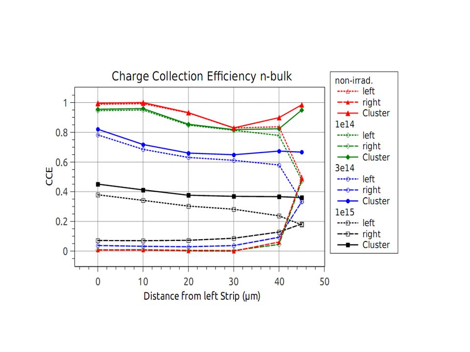
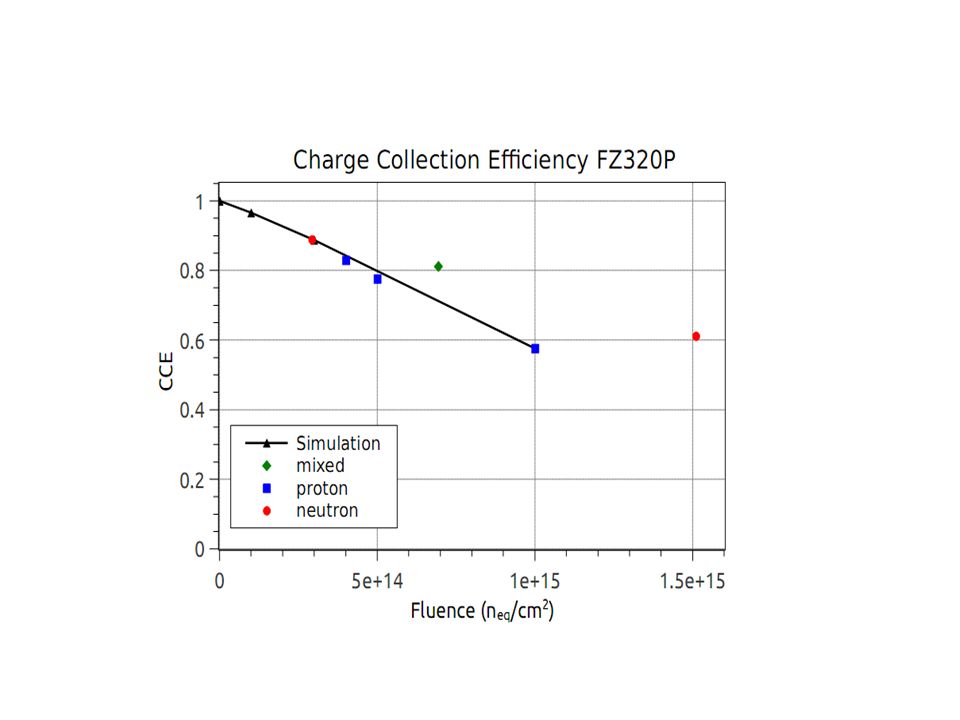
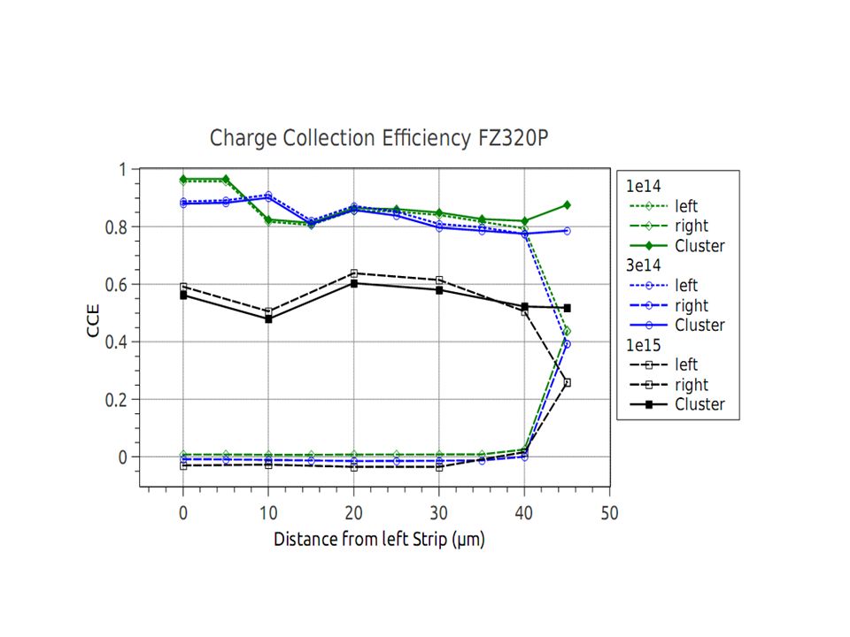
Charge Collection Efficiency

21
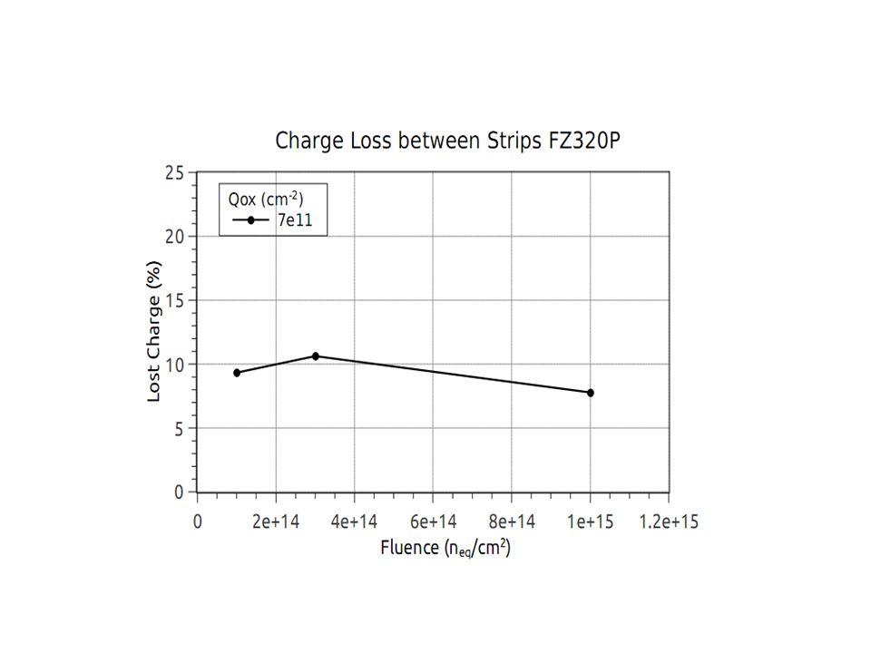
Charge Loss between Strips

Similar presentations
 O. Jinnouchi, R. Nagai (Tokyo.>")

Geometry layout: doping profiles for 3D geometry; 2) Results: electrostatic potential, electric field distribution;>")


 Y. Unno, S. Terada, T. Kohriki, Y. Ikegami (KEK) K. Yamamura,>")


1 G. PellegriniInstituto de Microelectrónica de Barcelona G. Pellegrini, C. Fleta, M. Lozano, D. Quirion, Ivan Vila, F. Muñoz.>")


 G. Kramberger, V. Cindro, I. Mandić, M. Mikuž Ϯ, M. Milovanović, M. Zavrtanik.>")


, O. Jinnouchi,>")
