Download presentation
Presentation is loading. Please wait.

1
SINE8I PROGRAM

2
AICSEC.word 162Ch,1h,4892h,67h ;Fs = 8 kHz This instruction sets the sampling frequency, fs, at 8 kHz.

3
SINE_ADDR.word SINE_VAL ;starting addr of sine values.brstart "SINE_BUFF",16 ;align sine table SINE_VAL.word 0,707,1000,707,0,-707,-1000,-707 ;sine values LENGTH.set 8 ;length of circular buffer These instructions initialize the starting address of the circular buffer. Note that the circular buffer must be of size 2 n. The length of circular buffer is 8 generating a frequency of 8 kHz/8 = 1 kHz.

4
BEGIN LDP AICSEC ;init to data page 128 This instruction establishes the data page register at 128. CALL AICSET_I ;init AIC This instruction calls the AICSET_I subroutine in the AICCOM31 program.

5
AIC Configuration (Chassaing P. 60)
")
6
AICSET_I Subroutine AICSET_I ;---CONFIG FOR INTERRUPT ----------- CALL AICSET ;call AICSET routine LDI 0h,IF ;clear IF register OR 10h,IE ;enable EXINT0 CPU interrupt OR 2000h,ST ;global interrupt enable RETS ;return from subroutine Call AICSET routine

7
Put of copy of these registers on the stack AICSET PUSH AR0 ;save AR0 PUSH AR1 ;save AR1 PUSH R0 ;save R0 PUSH R1 ;save R1 SP SP + 1 SP + 2 SP + 3 SP + 4

8
LDI @PBASE,AR0 ;AR0 -> 808000h LDI 1,R0 ;timer CLK=H1/2*(AIC master CLK) STI R0,*+AR0(28h) ;timer period reg(TCLK0=6.25 MHZ) AR0
 STI R0,*+AR0(28h) ;timer period reg(TCLK0=6.25 MHZ) AR0")
9
LDI 03C1h,R0 ;init timer global register STI R0,*+AR0(20h) ;reset timer AR0
 ;reset timer AR0")
10
03C1

11
AR0 xx INXF0OUTXF0I/OFX0I/OFX1INXF1OUTXF1 31-1615-1211-8765 4 3 2 1 0 IOF (IO Flag Register) 0 0 0 1 1 0 0 0 1 0 Configures XF0 as an output Put a 0 on XF0
 Configures XF0 as an output Put a 0 on XF0")
12
62H Place the AIC in reset by bringing XFO pin low. This is done by writing an 02 to the CPU’s IOF register.

13
809c03 809c04 809c05 AR1 809c06 162c 0001 4892 67 Contents of ATABLE = 809c03 This instruction establishes AR1 as a pointer to the table containing the information that sets the sampling frequency and the bandwidth of the antialiasing and reconstruction filters, as well as other constants used by the DSP.

15
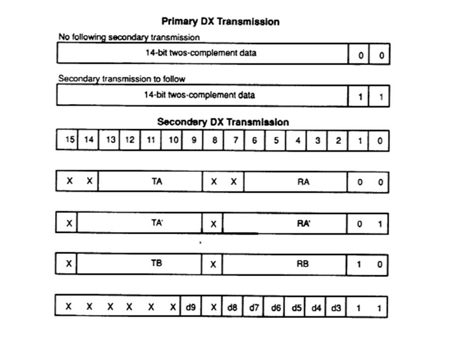
D15D14D13D12D11D10D9D8D6D5D4D3D7D2D1D0 XXXX0 0 0101101011 TA RA X X 1 0100100100100 162c Four values are defined in ATABLE. The first and third values define the sampling rate. TB RB 4892

16
D15D14D13D12D11D10D9D8D6D5D4D3D7D2D1D0 XXXX0 1 0000000000 T’A R’A The second value in table ATABLE sets TA’ and RA’ to zero implying that the sampling frequency will be determined only by TA and TB.

17
D15D14D13D12D11D10D9D8D6D5D4D3D7D2D1D0 XXX01 1 XXXXX11001 The fourth value of the table is the contents of the control register. Inserts antialiasing filter Disables loop- back function. Disables auxiliary input. Synchronous transmit receive sections The signal varies between 3 volts.

18
AR0

19
131

20
NOTE for this problem that the input A/D is not used. Only the D/A is used to generate the sine wave

21
AR0

22
FSXOUT XRDY RRDY XCLK SRCE DRP DXP CLKRP CLKXP RFSM XFSM RVAREN XVAREN RCLK SRCE HS RSR FULL XSR EMPTY SERIAL PORT GLOBAL CONTROL REGISTER 31 30 29 28 27 26 25 24 23 22 21 20 19 18 17 16 xx xx xx xx RRESET XRESET RINT RTINT XINT XTINT RLEN XLEN FSRP FSXP 15 14 13 12 11 10 9 8 7 6 5 4 3 2 1 0 0 0 0 0 0 0 1 1 0 0 0 0 0 0 0 0 0 0 0 0 1 1 1 0 1 0 0 1 0 0 0 0

23
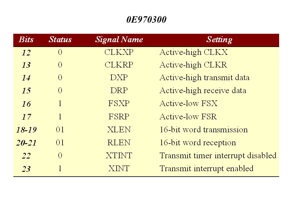
0E970300

25
The FSX and FSR frame syncs act as active-low inputs from the AIC. The DX and DR data signals remain active high. Both transmitted and received words are 16 bits in length. This configuration sets the serial port mode for a standard mode (i.e. not continuous mode) with a variable data rate. A variable data rate mode works with AIC’s timing protocol, whereas a fixed data rate mode does not.
 with a variable data rate. A variable data rate mode works with AIC’s timing protocol, whereas a fixed data rate mode does not..")
26
LDI 0,R0 ;R0 = 0 STI R0,*+AR0(48h) ;clear serial port XMIT register OR 06h,IOF ;bring AIC out of reset LDI 03h,RC ;RC=3 to transmit 4 values RPTB SECEND ;repeat 4 data transmit of sec com
 ;clear serial port XMIT register OR 06h,IOF ;bring AIC out of reset LDI 03h,RC ;RC=3 to transmit 4 values RPTB SECEND ;repeat 4 data transmit of sec com")
27
CALL TWAIT ;wait for data transmit LDI 03h,R0 ;value for secondary XMIT request STI R0,*+AR0(48h) ;secondary XMIT request to AIC CALL TWAIT ;wait for data transmit LDI *AR1++(1),R0 ;AR1 -> next AIC init data SECEND STI R0,*+AR0(48h) ;DTR = current AIC data POP R1 ;restore R1 POP R0 ;restore R0 POP AR1 ;restore AR1 POP AR0 ;restore AR0 RETS ;return from subroutine
 ;secondary XMIT request to AIC CALL TWAIT ;wait for data transmit LDI *AR1++(1),R0 ;AR1 -> next AIC init data SECEND STI R0,*+AR0(48h) ;DTR = current AIC data POP R1 ;restore R1 POP R0 ;restore R0 POP AR1 ;restore AR1 POP AR0 ;restore AR0 RETS ;return from subroutine")
Similar presentations

>")
>")


