Download presentation
Presentation is loading. Please wait.

1
Bubble Chamber Radiator Thermal Analysis 5.0 MeV, 9.5 MeV Beam Energy Fredrik Fors Mechanical Engineering 8/20/2015

2
Outline Background/Objective Analyzed Geometry Analysis Model Results Conclusion 7/22/2015 2

3
Overview Thermal analysis of radiator of a bubble chamber installation. A 3D solid FE model has been created and analyzed in ANSYS Workbench 16.1 Analysis includes deposited beam energy, surface-to-air convection and coolant tube. Results indicate maximum temperatures of: –704.2 K with 5.0 MeV, 200 µA beam –627.3 K with 9.5 MeV, 105 µA beam 7/22/2015 3

4
Analyzed Geometry The component assembly displayed below is included in the thermal analysis Flange, Tube (Stainless Steel) Coolant Loop (Copper) Radiator (Copper)
 Coolant Loop (Copper) Radiator (Copper)")
5
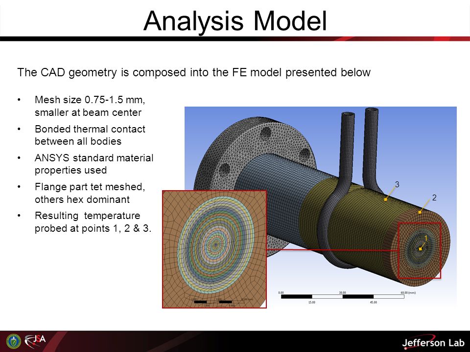
Analysis Model The CAD geometry is composed into the FE model presented below Mesh size 0.75-1.5 mm, smaller at beam center Bonded thermal contact between all bodies ANSYS standard material properties used Flange part tet meshed, others hex dominant Resulting temperature probed at points 1, 2 & 3. 3 1 2
6
Boundary Conditions The center front of the radiator is discretized into six 1 mm thick slices divided into 20 concentric areas, with 1 mm radial thickness. The power deposited by the beam is applied to these 120 bins according to a pre- calculated distribution. Only the rings with a power deposition of more than 10 -3 W/mm 3 are included for simplicity. In total this comprises 99.8% of the power to the radiator The analysis has been solved for 5.0 MeV and 9.5 MeV beam energy Convection BC representing surrounding air applied to outer surfaces of radiator and flange Convection BC representing coolant flow added to inner surface of coolant loop Outer Surfaces 6.0E-6 W/mm 2 /K 295 K (~22°C) Coolant Loop 2.81E-2 W/mm 2 /K 313.15 K (40°C)
 Coolant Loop 2.81E-2 W/mm 2 /K K (40°C).")
7
Max. temp: 704.16 K Results – 5.0 MeV In the plot below the resulting steady-state temperature is plotted on the model. Note that the display is sectioned through the central horizontal plane. Probe results: 1.704.2 K (431.0°C) 2.601.3 K (328.2°C) 3.474.3 K (201.2°C)
 K (328.2°C) K (201.2°C).")
8
Max. temp: 627.35 K Results – 9.5 MeV In the plot below the resulting steady-state temperature is plotted on the model. Note that the display is sectioned through the central horizontal plane. Probe results: 1.627.3 K (354.2°C) 2.567.8 K (294.6°C) 3.455.5 K (182.4°C)
 K (294.6°C) K (182.4°C).")
9
Conclusions

Similar presentations

, October.>")

 (Section 3.5 – Textbook) 3.1 Implications of energy generation Involve.>")


>")


