Download presentation
Presentation is loading. Please wait.

1
Traditionally ladder logic programs have been written by thinking about the process and then beginning to write the program. This always leads to programs that require debugging. And, the final program is always the subject of some doubt. Structured design techniques, such as Boolean algebra, lead to programs that are predictable and reliable. The structured design techniques is to make ladder logic design routine and predictable for simple sequential systems. Structure Logic Design

2
Structured Design Structured design is very important in engineering, but many engineers will write software without taking the time or effort to design it. This often comes from previous experience with programming where a program was written, and then debugged. This approach is not acceptable for mission critical systems such as industrial controls. The time required for a poorly designed program is 10% on design, 30% on writing, 40% debugging and testing, 10% documentation. The time required for a high quality program design is 30% design, 10% writing software, 10% debugging and testing, 10% documentation.

3
Time to Design If you are spending time debugging ladder logic programs you are doing something wrong. Structured design also allows others to verify and modify your programs. If you are spending time debugging ladder logic programs you are doing something wrong. Structured design also allows others to verify and modify your programs. Axiom: Spend as much time on the design of the program as possible. Resist the temptation to implement an incomplete design.

4
Sequential System Most control systems are sequential in nature. During normal operation these systems will have multiple steps or states of operation. In each operational state the system will behave differently. Typical states include start-up, shut- down, and normal operation.

5
Traffic Light Consider a set of traffic lights - each light pattern constitutes a state. Lights may be green or yellow in one direction and red in the other. The lights change in a predictable sequence. Sometimes traffic lights are equipped with special features such as cross walk buttons that alter the behavior of the lights to give pedestrians time to cross busy roads

6
Sequential Design Techniques

7
A typical machine will use a sequence of repetitive steps that can be clearly identified. Ladder logic can be written that follows this sequence. The steps for this design method are: 1. Understand the process. 2. Write the steps of operation in sequence and give each step a number. 3. For each step assign a bit. 4. Write the ladder logic to turn the bits on/off as the process moves through its states. 5. Write the ladder logic to perform machine functions for each step. 6. If the process is repetitive, have the last step go back to the first.

8
Case Study Consider the example of a flag raising controller. The problem begins with a written description of the process. This is then turned into a set of numbered steps. Each of the numbered steps is then converted to ladder logic.

9
Case Study Description: A flag raiser that will go up when an up button is pushed, and down when a down button is pushed, both push buttons are momentary. There are limit switches at the top and bottom to stop the flag pole. When turned on at first the flag should be lowered until it is at the bottom of the pole.

10
Case Study Steps: 1. The flag is moving down the pole waiting for the bottom limit switch. 2. The flag is idle at the bottom of the pole waiting for the up button. 3. The flag moves up, waiting for the top limit switch. 4. The flag is idle at the top of the pole waiting for the down button.

11
Ladder Diagram Using Latch Bit

13
Process Sequence Bits Without Latches

15
Flowchart Based Design A flowchart is ideal for a process that has sequential process steps. The steps will be executed in a simple order that may change as the result of some simple decisions. The symbols used for flowcharts are as shown below.

16
Flowchart Symbols

17
These blocks are connected using arrows to indicate the sequence of the steps. The different blocks imply different types of program actions. Programs always need a start block, but PLC programs rarely stop so the stop block is rarely used. Other important blocks include operations and decisions. The other functions may be used but are not necessary for most PLC applications.

18
Case Study A flowchart is shown in the next slide is for a control system for a large water tank. When a start button is pushed the tank will start to fill, and the flow out will be stopped. When full, or the stop button is pushed the outlet will open up, and the flow in will be stopped.

20
Operation The first operation is to open the outlet valve and close the inlet valve. Next, a single decision block is used to wait for a button to be pushed. when the button is pushed the yes branch is followed and the inlet valve is opened, and the outlet valve is closed. Then the flow chart goes into a loop that uses two decision blocks to wait until the tank is full, or the stop button is pushed

21
Operation If either case occurs the inlet valve is closed and the outlet valve is opened. The system then goes back to wait for the start button to be pushed again. When the controller is on the program should always be running, so only a start block is needed. Many beginners will neglect to put in checks for stop buttons

22
Steps The general method for constructing flowcharts is: 1. Understand the process. 2. Determine the major actions, these are drawn as blocks. 3. Determine the sequences of operations, these are drawn with arrows 4. When the sequence may change use decision blocks for branching.

23
Steps Once a flowchart has been created ladder logic can be written. There are two basic techniques that can be used, the first presented uses blocks of ladder logic code. The second uses normal ladder logic.

24
Name Each Block The first step is to name each block in the flowchart. Each of the numbered steps will then be converted to ladder logic

26
MCR Each block in the flowchart will be converted to a block of ladder logic. To do this we will use the MCR (Master Control Relay) instruction. The instruction will appear as a matched pair of outputs labelled MCR. If the first MCR line is true then the ladder logic on the following lines will be scanned as normal to the second MCR. If the first line is false the lines to the next MCR block will all be forced off. If a normal output is used inside an MCR block, it may be forced off. Therefore latches will be used in this method.
 instruction. The instruction will appear as a matched pair of outputs labelled MCR. If the first MCR line is true then the ladder logic on the following lines will be scanned as normal to the second MCR. If the first line is false the lines to the next MCR block will all be forced off. If a normal output is used inside an MCR block, it may be forced off. Therefore latches will be used in this method..")
27
MCR

28
Ladder Logic Design The first part of the ladder logic required will reset the logic to an initial condition. The line will only be true for the first scan of the PLC, and at that time it will turn on the flowchart block F1 which is the reset all values off operation. All other operations will be turned off.

34
Convert to Sequential Bit – Add Transitions

35
Transition Logic

36
Function Logic and Output

37
Practical Problem Convert the following flow chart to ladder logic Convert the following flow chart to ladder logic

38
Solution

39
Solution

40
Solution

41
SFC All of the previous methods are well suited to processes that have a single state active at any one time. This is adequate for simpler machines and processes, but more complex machines are designed perform simultaneous operations. This requires a controller that is capable of concurrent processing - this means more than one state will be active at any one time. This could be achieved with multiple state diagrams, or with more mature techniques such as Sequential Function Charts

42
SFC Sequential Function Charts (SFCs) are a graphical technique for writing concurrent control programs.
 are a graphical technique for writing concurrent control programs.")
43
Sequential Function Chart Sequential function chart (SFC) is a graphical language, which makes it possible to depict sequential behaviour. Sequential function chart (SFC) is a graphical language, which makes it possible to depict sequential behaviour. It displays the process flow as a diagram One of the most important aspects of SFC is that it shows the main states of a system, all the possible changes of state and the reasons why those changes would occur. It can be used at the top level to show the main phases of a process, but it can also be used at any other lower level. One of the most important aspects of SFC is that it shows the main states of a system, all the possible changes of state and the reasons why those changes would occur. It can be used at the top level to show the main phases of a process, but it can also be used at any other lower level.
 is a graphical language, which makes it possible to depict sequential behaviour. It displays the process flow as a diagram One of the most important aspects of SFC is that it shows the main states of a system, all the possible changes of state and the reasons why those changes would occur. It can be used at the top level to show the main phases of a process, but it can also be used at any other lower level. One of the most important aspects of SFC is that it shows the main states of a system, all the possible changes of state and the reasons why those changes would occur. It can be used at the top level to show the main phases of a process, but it can also be used at any other lower level..")
44
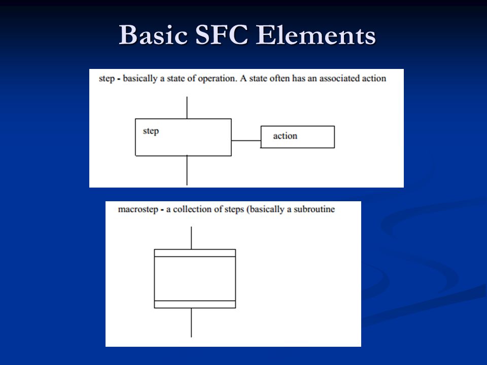
SFC A SFC consists of the following elements. A number of steps; these steps are being depicted by rectangular boxes. Each step represents a particular state of the system being controlled. At least one of these steps is the initial step, which is depicted by a rectangular box containing vertical bars. The initial step is the first step to be activated whenever a SFC is started. The steps are connected by transitions. A line between two steps depicts a transition. Each transition is associated with a condition. When a condition following an active step becomes true, this results in the next step being activated and the active step becoming deactivated. Each step is associated with some action, performed while the step is active. Actions can be described by any of the five languages defined by the IEC 1131-3 standard.

45
Basic SFC Elements

47
SFC Branch

48
SFC SFC is suitable for understanding the processing order and status transition of a program.

49
Elements of SFC

50
Elements of SFC Elements of SFC

51
Example of SFC Action Qualifiers: Nnon-stored, executes while the step is active Rresets a store action Ssets an action active Ltime limited action, terminates after a given period Dtime delayed action. Pa pulse action, executes once in a step SDstored and time delayed DStime delayed and stored SLstored and time limited

52
SFC for the Robot Process

53
Case Study: SFC for Parking Lot

54
Case Study Refer to slides for Parking Lot SFC Refer to slides for Parking Lot SFC

55
Q: Q: Convert the following Sequential Function Chart to its equivalent ladder diagram.

56
Solution

58
Solution

59
Q: Q: Draw an SFC for a stamping press that can advance and retract when a cycle button is pushed, and then stop until the button is pushed again. Use limit switches to detect fully advanced or retract.

60
Solution

61
Case Study: Tea Maker

62
Solution

63
Case Study: Industrial Control

64
Solution

Similar presentations