Download presentation
Presentation is loading. Please wait.

1
RESISTIVE CIRCUIT Topic 2

2
Series/parallel resistor Voltage divider circuit
RESISTIVE CIRCUIT Series/parallel resistor Voltage divider circuit Current divider circuit Voltage and current measurement Wheatstone bridge Delta-wye (Pi-Tee) equivalent circuit
 equivalent circuit.")
3
SERIES/PARALLEL RESISTOR
Resistors that are arranged in series: Resistance equivalent Req = R1 + R2 + ……….+ RN

4
CURRENT IN SERIES CIRCUIT
Current in series circuit is same at all circuit elements VOLTAGE IN SERIES CIRCUIT Voltage (VT) in series circuit is the total of voltage for each elements.
 in series circuit is the total of voltage for each elements.")
5
Resistors that are arranged in parallel:

6
Resistance equivalent:

7
For circuits with two resistors in parallel:

8
CURRENT IN PARALLEL CIRCUIT
Current in parallel circuits is the total current for each of the circuit elements. VOLTAGE IN PARALLEL CIRCUIT Voltage (VT) for parallel circuits is the same for all circuits elements
 for parallel circuits is the same for all circuits elements.")
9
Series/parallel resistor Voltage divider circuit
RESISTIVE CIRCUIT Series/parallel resistor Voltage divider circuit Current divider circuit Voltage and current measurement Wheatstone bridge Delta-wye (Pi-Tee) equivalent circuit
 equivalent circuit.")
10
VOLTAGE DIVIDER 1 R 2 V _ + I -

11
Using Ohm law, we will get:
Voltage at resistor R2:

12
Series/parallel resistor Voltage divider circuit
RESISTIVE CIRCUIT Series/parallel resistor Voltage divider circuit Current divider circuit Voltage and current measurement Wheatstone bridge Delta-wye (Pi-Tee) equivalent circuit
 equivalent circuit.")
13
CURRENT DIVIDER

14
Using Ohm law, (1)
")
15
From equation (1):
:")
16
Series/parallel resistor Voltage divider circuit
RESISTIVE CIRCUIT Series/parallel resistor Voltage divider circuit Current divider circuit Voltage and current measurement Wheatstone bridge Delta-wye (Pi-Tee) equivalent circuit
 equivalent circuit.")
17
VOLTAGE AND CURRENT MEASUREMENT
An ammeter is an instrument designed to measure current. It is placed in series with the circuit element whose current is being measured. An ideal ammeter has an equivalent resistance of 0Ω and functions as a short circuit in series with the element whose current is being measured.

18
A voltmeter is an instrument designed to measure voltage.
It is placed in parallel with the element whose voltage is being measured. An ideal voltmeter has an infinite equivalent resistance and thus functions as an open circuit in parallel with the element whose voltage is being measured.

19
The configurations for an ammeter and voltmeter to measure current and voltage

20
Series/parallel resistor Voltage divider circuit
RESISTIVE CIRCUIT Series/parallel resistor Voltage divider circuit Current divider circuit Voltage and current measurement Wheatstone bridge Delta-wye (Pi-Tee) equivalent circuit
 equivalent circuit.")
21
WHEATSTONE BRIDGE The Wheatstone bridge circuit is used to precisely measure resistance of medium values, that is in the range of 1Ω to 1MΩ. The bridge circuit consists of four resistors, a dc voltage source and a detector.

22
The Wheatstone bridge circuit:

23
When the bridge is balanced:
Combining these equation, gives

24
Solving these equation, yields

25
Series/parallel resistor Voltage divider circuit
RESISTIVE CIRCUIT Series/parallel resistor Voltage divider circuit Current divider circuit Voltage and current measurement Wheatstone bridge Delta-wye (Pi-Tee) equivalent circuit
 equivalent circuit.")
26
DELTA-WYE (PI-TEE) CIRCUIT
If the galvanometer in Wheatstone bridge is replace with its equivalent resistance Rm,

27
The resistor R1, R2 and Rm (or R3, Rm dan Rx) are referred as a delta (∆) interconnection. It also is referred as a pi (π) interconnection because the ∆ can be shaped into a π without disturbing the electrical equivalance of the two confiurations.
 interconnection because the ∆ can be shaped into a π without disturbing the electrical equivalance of the two confiurations..")
28
Delta configuration

29
The resistors R1, Rm and R3 (or R2, Rm and Rx) are referred as a wye (Y) interconnection because it can be shaped to look like the letter Y. The Y configuration also referred as a tee (T) interconnection.
 interconnection..")
30
Wye configuration

31
The ∆ - Y transformation

32
Using series and parallel simplifications in Δ-connected, yield

33
Using straightforward algebraic manipulation gives,

34
The expression for the three Δ-connected resistors as functions of three Y-connected resistors are

35
EXAMPLE 1 Find the current and power supplied by the 40V sources in the circuit shown below.

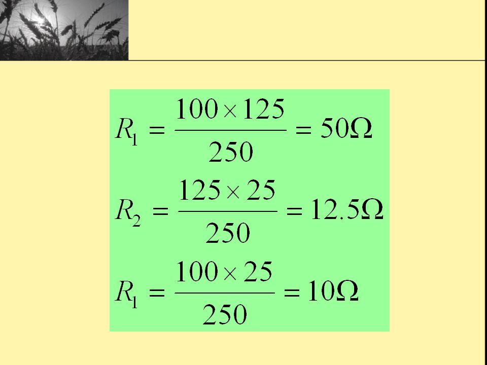
36
We can find this equivalent resistance easily after replacing either the upper Δ (100, 125, 25Ω) or the lower Δ (40, 25, 37.5Ω) with its equivalent Y. We choose to replace the upper Δ. Thus,

38
Substituting the Y-resistor into the circuit,

39
The equivalent circuit,

40
Calculate the equivalent resistance,

41
Simplification of the circuit,

42
Then, the current and power values are,

43
Example 2

44
Find no load value of vo. Find vo when RL = 150kΩ How much power is dissipated in the 25kΩ resistor if the load terminals are accidentl short-circuited?

45
Answer: a) b)
 b)")
46
c)
")
47
EXAMPLE 3 Find the power dissipated in the 6Ω resistor.

48
Equivalent resistance
Asnwer Equivalent resistance current io,

49
Note that io is the current in the 1.6Ω resistor.
Use current divider to get current in the 6Ω resistor,

50
Then the power dissipated by the resistor is

51
EXAMPLE 4 Find the voltage of vo and vg.

52
Asnwer Equivalent resistance Current in resistor 30Ω

53
Voltage v0 Total voltage at the resistor

54
Voltage vg

55
EXAMPLE 5 Find the current of ig and.io

56
Equivalent resistance:
Answer Equivalent resistance:

57
Current values,

58
Thus,

59
EXAMPLE 6 Determine the value of io

Similar presentations
 Find the currents i1 and i2 in the circuit in the figure. b) Find the voltage vo. c) Verify that the total power developed equals the total power.>")


