Download presentation
Presentation is loading. Please wait.

1
The Tools of Subsurface Analysis

2
Well Logs Delimit of surfaces & identify sediments penetrated
Resistivity Logs Spontaneous Potential (SP) Logs Gamma Ray Logs Neutron Logs Density Logs Sonic (acoustic) Logs
 Logs. Gamma Ray Logs. Neutron Logs. Density Logs. Sonic (acoustic) Logs.")
3
Well Logs Delimit of surfaces & identify sediments penetrated
Resistivity Logs Spontaneous Potential (SP) Logs Gamma Ray Logs Neutron Logs Density Logs Sonic (acoustic) Logs
 Logs. Gamma Ray Logs. Neutron Logs. Density Logs. Sonic (acoustic) Logs.")
4
Well Logs Delimit of surfaces & identify sediments penetrated
Resistivity Logs Spontaneous Potential (SP) Logs Gamma Ray Logs Neutron Logs Density Logs Sonic (acoustic) Logs
 Logs. Gamma Ray Logs. Neutron Logs. Density Logs. Sonic (acoustic) Logs.")
5
Well Logs Delimit of surfaces & identify sediments penetrated
Resistivity Logs Spontaneous Potential (SP) Logs Gamma Ray Logs Neutron Logs Density Logs Sonic (acoustic) Logs
 Logs. Gamma Ray Logs. Neutron Logs. Density Logs. Sonic (acoustic) Logs.")
6
Well Logs Delimit of surfaces & identify sediments penetrated
Resistivity Logs Spontaneous Potential (SP) Logs Gamma Ray Logs Neutron Logs Density Logs Sonic (acoustic) Logs
 Logs. Gamma Ray Logs. Neutron Logs. Density Logs. Sonic (acoustic) Logs.")
7
The Tools of Subsurface Analysis
Facies analysis of subsurface data depends on tools which delimit of surfaces and provide clues as to the sediments they contain: Well logs Cores Seismic Gravity & magnetics GEOL 553 Lecture 3; Subsurface Analysis

8
Well Logs Versus Seismic
Great vertical resolution Delimit bounding surfaces Establish lithology of sediments penetrated Seismic Great lateral continuity and resolution Define gross sediment geometry

9
Tools are Keys to Allostratigraphy & Sequence Stratigraphy
bounding discontinuities including erosion surfaces, marine flooding surfaces, tuffs, tempestite, and/or turbidite boundaries etc. as time markers Sequence Stratigraphy: higher level allostratigraphic model which interprets depositional origin of sedimentary strata as products of "relative sea level change"

10
The Tools of Subsurface Analysis
Facies analysis of subsurface data depends on tools which delimit of surfaces and provide clues as to the sediments they contain: Well logs Seismic

11
Well Logs Delimit of surfaces & identify sediments penetrated
Resistivity Logs Spontaneous Potential (SP) Logs Gamma Ray Logs Neutron Logs Density Logs Sonic (acoustic) Logs
 Logs. Gamma Ray Logs. Neutron Logs. Density Logs. Sonic (acoustic) Logs.")
14
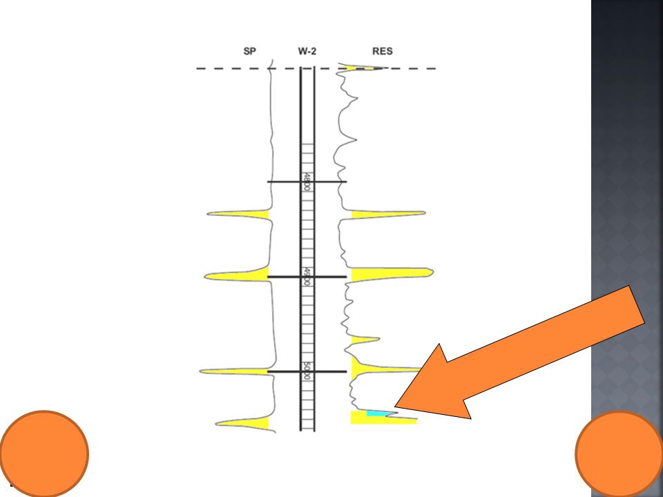
Resistivity Logs The most commonly used logs:
Measures resistance of flow of electric current Is function of porosity & pore fluid in rock Frequently used to identify lithology

16
Spontaneous Potential (SP) Logs
Next most common log Measures electrical current in well Result of salinity differences between formation water and the borehole mud Separates bed boundaries of permeable sands & impermeable shales.

18
Gamma Ray Logs Another common log Records radioactivity of a formation
Shales have high gamma radioactive response Gamma ray logs infer grain size (and so subsequently inferred depositional energy) Gamma ray logs are most commonly used logs for sequence stratigraphic analysis
 Gamma ray logs are most commonly used logs for sequence stratigraphic analysis.")
19
GEOL 553 Lecture 3; Subsurface Analysis

20
GEOL 553 Lecture 3; Subsurface Analysis

21
GEOL 553 Lecture 3; Subsurface Analysis
After Harris & Saller 1999

22
Neutron Logs Another common log Measures porosity of formation
Uses quantity of hydrogen present Measures lithology when used with Density Log

23
Density Logs A common log Measures formation’s bulk density
Used as a porosity measure Differentiates lithologies with Neutron Log Used with Sonic Logs to generate synthetic seismic traces to match to seismic lines

24
Sonic (Acoustic) Logs Another common log
Measures of speed of sound in formation Tied to porosity and lithology Used with Density Logs to generate Synthetic Seismic traces to match to Seismic lines

27
The Tools of Subsurface Analysis
Facies analysis of subsurface data depends on tools which delimit of surfaces and provide clues as to the sediments they contain: Well logs Seismic

28
Seismic Seismic stratigraphic interpretation used to:
Define geometries of genetic reflection packages that envelope seismic sequences and systems tracts Identify bounding discontinuities on basis of reflection termination patterns and continuity

29
Seismic Boundaries Termination below discontinuity, or upper sequence boundary : Toplap termination Truncation of sediment surface Often channel bottom Above a discontinuity defining lower sequence boundary: Onlap over surface Downlap surface

30
Seismic Boundaries Below Boundary - Toplap termination

31
Seismic Boundaries Below Boundary - Truncation of surface

32
Seismic Boundaries Channeled Surface – Below Boundary

33
Seismic Boundaries Over Boundary - Onlap onto surface

34
Seismic Boundaries Over Boundary- Downlap onto surface

35
GEOL 553 Lecture 3; Subsurface Analysis

36
GEOL 553 Lecture 3; Subsurface Analysis

37
GEOL 553 Lecture 3; Subsurface Analysis

39
Sequence Stratigraphy
Subdivision & interpretation of sedimentary record using a framework surfaces seen in outcrops, well logs, & 2-D and 3-D seismic. Include: Surfaces of erosion & non-deposition (sequence boundaries) Flooding (trangressive surfaces [TS] &/or maximum flooding surfaces [mfs]) & high stand condensed surfaces This framework used to predict the extent of sedimentary facies geometry, lithologic character, grain size, sorting & reservoir quality
 Flooding (trangressive surfaces [TS] &/or maximum flooding surfaces [mfs]) & high stand condensed surfaces. This framework used to predict the extent of sedimentary facies geometry, lithologic character, grain size, sorting & reservoir quality.")
40
Tools Define Bounding Surfaces
These surfaces subdivide sedimentary rock & provide:- Relative time framework for sedimentary succession Better understanding of inter-relationship of depositional settings & their lateral correlation Conceptual models follow that link the processes that formed the sediments and enable the prediction of their gross geometries

41
Hierarchy of Geometries
Sequence geometries are subdivided and defined by Maximum Flooding Surfaces (mfs) Transgressive Surfaces (TS) Sequence Boundaries (SB) Define how vertical succession or stacking patterns of unconfined sheets are arranged Prograde (step seaward) Retrograde (step landward) Aggrade (build vertically) Sheets and unconfined lobes may contain Non-amalgamated bodies Amalgamated, multi-storied bodies Incised topographic fill of valleys Unconfined but localized lobes from point & multiple up dip sources Unconfined but localized build ups (carbonates)
 Transgressive Surfaces (TS) Sequence Boundaries (SB) Define how vertical succession or stacking patterns of unconfined sheets are arranged. Prograde (step seaward) Retrograde (step landward) Aggrade (build vertically) Sheets and unconfined lobes may contain. Non-amalgamated bodies. Amalgamated, multi-storied bodies. Incised topographic fill of valleys. Unconfined but localized lobes from point & multiple up dip sources. Unconfined but localized build ups (carbonates)")
46
Delta Mouth Bar - Kentucky
Note Incised Surface

47
Channel – Gulf Coast Note Incised Surface
GEOL 553 Lecture 3; Subsurface Analysis

48
Flood Deltas & Channels - Kty
GEOL 553 Lecture 3; Subsurface Analysis

49
Tidal Channels Khor al Bazam - UAE

50
Tidal, Storm or Tsunami Channel
Note Incised Surface GEOL 553 Lecture 3; Subsurface Analysis

51
Tsunami Load & Drape - Kty
Note Uniform Thickness of Layer GEOL 553 Lecture 3; Subsurface Analysis

52
Clastic Sequence Stratigraphic Hierarchies
GEOL 553 Lecture 3; Subsurface Analysis

53
Channels & Shelves Shelf Channel
Both have unique processes & structures that can be used to identify their setting

54
Tools Enable Sequence Stratigraphic Analysis
This analysis involves Subdivision of section into sequences, parasequences and beds. Link conceptual models with mix of components of the individual sequence, parasequence or beds Use these to explain the depositional setting in terms of their lithology, grain size, sedimentary structures, contacts character (gradational, abrupt) etc
 etc.")
55
Sequence Stratigraphic Analysis
GEOL 553 Lecture 3; Subsurface Analysis

58
Unconfined Flow - Not in a Channel
Unique Processes Flow is in all directions No lateral boundaries, only upper and lower boundaries Velocity changes: high to low Sediment responses Decrease in grain size: Fining outward (coarse to fine) Erosional/sharp/gradational contacts Accretion: Downstream, upstream and vertical Decrease in sedimentary structures away from source Geometries Sheets Thin in direction of flow
 Erosional/sharp/gradational contacts. Accretion: Downstream, upstream and vertical. Decrease in sedimentary structures away from source. Geometries. Sheets. Thin in direction of flow.")
59
End of the Lecture Can it be supper time?

Similar presentations