Download presentation
Presentation is loading. Please wait.

1
VARIABLE FREQUENCY DRIVES

2
Need for variable frequency drives Match the Torque of a drive to the process requirements Match the Speed of a drive to the process requirements Save Energy and improve efficiency

3
X Smooth acceleration/deceleration to..... l Reduce mechanical wear and water hammer l Reduce current surges in the power supply system X Energy savings are possible..... l Most significant with centrifugal pumps and fans because l Power/energy consumption changes with Speed 3 X Speed controlled to match the process requirements.... e.g.... flow or pressure controlled to match demand X Automatic Control of the Process Variable is possible l Closed loop control from a Process Controller Need for variable frequency drives

4
Variable speed – Energy consumption X Principles applied to centrifugal Pumps and Fans

5
X Compare two methods of speed control in a Motor Car.... l Speed controlled using Drive Control (A B) l Speed controlled by using Load Control (A C) Variable speed – Energy consumption
 l Speed controlled by using Load Control (A C) Variable speed – Energy consumption.")
6
Common example of VS control X The Motor Car is a common example of VS control l Control Torque to provide Acceleration and Braking l Controls Speed to match the traffic conditions l Controls the use of Fuel X Main controls in a Motor Car are : l Accelerator, which controls the Driving torque l Brake, which adjusts the Load torque l Control System.... the driver

7
4 – Quadrant drive

8
X 1st QUADRANT..... Torque is +ve and Speed is +ve l Therefore..... Power is +ve l Energy transferred from Drive to Load X 2nd QUADRANT..... Torque is -ve and Speed is +ve l Therefore..... Power is -ve l Energy transferred from Load to Drive.... Braking X 3rd QUADRANT..... Torque is -ve and Speed is -ve l Therefore..... Power is +ve l Energy transferred from Drive to Load X 4th QUADRANT..... Torque is +ve and Speed is -ve. l Therefore..... Power is -ve l Energy transferred from Load to Drive.... Braking 4 – Quadrant drive

9
Fundamental principles X Power is Rate at which Work is being done by a machine l Power is measured in Watts, or usually kW or MW l Power is product of Torque x Speed l At standstill.... Output Power = Zero X Energy represents the work done over a period of time l Energy is the product of Power x Time l Energy is measured as kiloWatt-hours.... kWh

10
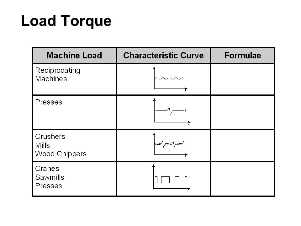
Load Torque

12
Torque – Speed curves X Torque, Power & Speed are the most important parameters X Torque-Speed curves illustrate the performance of the VSD l shows the rotational force at various speeds X Power-Speed curves illustrate the performance of the VSD l shows the rate of energy consumption at various speeds X These parameters are all related... for example the Motor Car l Pressing the accelerator produces more torque.... which provides acceleration and gives more speed.... which requires more power (torque x speed).... which requires more energy (fuel) (power x time)
.... which requires more energy (fuel) (power x time).")
13
Types of variable speed drives X Mechanical Variable Speed Drives l Belt and chain drives with adjustable diameter sheaves l Metallic friction drives X Hydraulic Variable Speed Drives l Hydrodynamic types l Hydrostatic types X Electrical Variable Speed Drives l DC Drive with DC motor l VVVF Converter with AC motor l Slip Control with Slip ring Induction Motor l Cyclo-converter with AC motor l Electromagnetic Coupling or "Eddy Current" Coupling l Servo Drives and Stepper Drives

14
Common types of variable frequency drives

15
Migration from DC to AC drives

16
Principles of AC variable drives X Speed controlled by adjusting the Power Frequency (f) l Synchronous Speed X Actual speed is slower due to the Slip l Actual Speed X Stator field flux ( ) is derived from the supply voltage l Air-gap Flux X Output Torque is product of flux density and rotor current I R l Output Torque
 l Synchronous Speed X Actual speed is slower due to the Slip l Actual Speed X Stator field flux ( ) is derived from the supply voltage l Air-gap Flux X Output Torque is product of flux density and rotor current I R l Output Torque")
17
AC Variable speed drive From these equations, the following deductions can be made X Speed is controlled by Frequency AND Stator Voltage X Speed reaches Base Speed when V S = maximum, l Further speed increase reduces the Field Flux l This is known as the Field Weakening range X Torque is dependent on V S l Full torque possible at ALL speeds in normal speed range l But Torque falls to zero at standstill X In the Normal Speed range l Output power increases in proportion to the speed X In the Field Weakening range, l Torque falls in proportion to the speed l Output power of the AC Motor remains constant

18
AC Variable speed drive

19
X Main Features of the AC Variable Speed Drive l Good control and performance characteristics l AC converter relatively complex and expensive l AC Motor needs no maintenance... high reliability l Efficiency : Converter ± 97%... overall AC drive >90%

20
Basic definitions X Rectifier... AC to DC converter X Inverter … DC to AC converter

21
X AC Converter converts one AC voltage and frequency to another AC voltage and frequency.... often variable X Usually requires an intermediary DC link with smoothing Basic definitions

22
X DC Converter... Converts one DC voltage to another DC voltage X Usually requires an intermediary AC link, such as a transformer Basic definitions

23
X Electronic Switch....... l Electronically connects or disconnects an AC or DC circuit l Can often be switched ON or OFF from a gate terminal Basic definitions

24
Bistable switching X Electronic Switch usually operated in the bistable mode l Blocking Mode :fully switched OFF Voltage across switch is High Current through switch is Low (only leakage current) l Conducting Mode :fully switched ON Voltage across the component is Low Current through the component is High X Diodes, Thyristors & GTOs are inherently bistable X Transistors are NOT inherently bistable l Must be biased fully ON or OFF to behave like a bistable device
 l Conducting Mode :fully switched ON Voltage across the component is Low Current through the component is High X Diodes, Thyristors & GTOs are inherently bistable X Transistors are NOT inherently bistable l Must be biased fully ON or OFF to behave like a bistable device")
25
Power diodes IDEAL :Forward Conduction: Resistanceless Reverse Blocking: Lossless Switch on/off Time: Instantaneous X Main terminals are the Anode (A) and the Cathode (K) l Names come from the days when Valves were common X When the anode is positive relative to the cathode l it is said to be forward biased and the diode conducts X When the anode is negative relative to the cathode l is said to be reverse biased and current is blocked
 and the Cathode (K) l Names come from the days when Valves were common X When the anode is positive relative to the cathode l it is said to be forward biased and the diode conducts X When the anode is negative relative to the cathode l is said to be reverse biased and current is blocked")
26
X Many different mechanical designs are used X Rated from a few amps … to thousands of amps X Most common is for several diodes to be encapsulated into an Insulated Module... 6-pulse bridge, half bridge, etc X The base of the module electrically isolated... Can be mounted directly onto heatsink Power diodes

27
Bipolar junction transistor X Main advantage of Bipolar Junction Transistors (BJT).... l Turned on and off from the base terminal l Suitable for Self commutated inverter circuits X Disadvantage is low base amplification factor.... 5 to 10 l base circuit must be driven by an auxiliary transistor l called the Darlington connection

28
Field effect transistor X FET is a special type of transistor... l particularly suitable for high speed switching applications l Gate is voltage controlled.... not current controlled l behaves like a HF voltage controlled resistance X MOSFET is a three terminal device l Source (S), Drain (D) and the Gate (G) l correspond to Emitter (E), Collector (C) and Gate (G) of BJT
, Drain (D) and the Gate (G) l correspond to Emitter (E), Collector (C) and Gate (G) of BJT.")
29
Field effect transistor X MOSFET is a majority carrier device.... short switching time l so... switching losses are low l best suited to high frequency switching applications X With development of Pulse Width Modulated (PWM) inverter l high frequency switching has become a desirable feature l to provide a smooth output current waveform X MOSFETs are used for Small PWM frequency converters l MOS stands for Metal Oxide Silicon. l Ratings from 100Amp @ 50Volt to 5Amp @ 1000Volt
 inverter l high frequency switching has become a desirable feature l to provide a smooth output current waveform X MOSFETs are used for Small PWM frequency converters l MOS stands for Metal Oxide Silicon. l Ratings from 50Volt to 1000Volt.")
30
Insulated gate bipolar transistor X Insulated Gate Bipolar Transistor (IGBT)..... l unites best features of BJT and MOSFET technologies l Construction similar to a MOSFET with additional layer to l provide conductivity modulation, similar to BJT l low conduction voltage drop X IGBT is a three terminal device.... l Power terminals are called Emitter (E) and Collector (C) l Control terminal is called the Gate (G)
 and Collector (C) l Control terminal is called the Gate (G).")
31
X IGBT has...... good forward blocking ability l very limited reverse blocking ability l Operates at higher current densities than BJT or MOSFET X Electrical equivalent circuit of the IGBT.... hybrid device l MOSFET driver integrated with a Bipolar PNP transistor Insulated gate bipolar transistor

32
X Gate driver requirements similar to those of power MOSFET l Turn-on : 10V - 15V takes 1 s.... Threshold typically 4V l Turn-off : zero volts takes 2 s... accelerated by -ve volts X IGBT devices can be produced with faster switching times at the expense of increased forward voltage drop X Main advantages of IGBT are : l Good power handling capabilities.... 500A at 1,500V l Low forward conduction voltage drop of 2V to 3V … higher than BJT but lower than MOSFET of similar size l Gate is voltage controlled with low gate current l Relatively simple voltage controlled gate driver l High speed switching capability.... up to about 20kHz l V F increases with temperature.... making device suitable for parallel operation... without thermal instability Insulated gate bipolar transistor

33
Comparison of PE switches

34
Overall control system X Overall Control System divided into 4 main areas : l Inverter Control System l Speed Control System and Speed feedback l Current (Torque) Control System and Current feedback l External System Control Interface
 Control System and Current feedback l External System Control Interface")
35
Overall control system X Inverter Control System l Controls the Switching Sequence of Inverter Switches l Provides Component Protection X Speed feedback and Speed Control System l Controls the Speed output relative to Setpoint X Current Control System and Current feedback l Controls the Current output relative to Limits l Provides Short-circuit and Earth-Fault Protection l Motor Modelling and Thermal Overload Protection X External System Control Interface l User Settings and Programming l Digital and Analog interface to Control System (PLCs) l Fault Diagnostics
 l Fault Diagnostics")
36
Power supply requirements X Simplest Method for Power Supply... Mains Transformer l Major problem... interruption of the Mains Power l VSD Stops... even for short dips in the supply X Commonly use Switched Mode Power Supplies (SMPS) l Control power maintained until motor stops l Mains failure... power initially from large DC Capacitors l Thereafter... motor behaves as AC induction generator X Usually have several Power Supplies to modules such as... l Device Driver Power Supplies need to be isolated l Cooling fans for the converter heatsinks l DC Link Bus Charging Circuits l Control Cards.... Microprocessor circuits
 l Control power maintained until motor stops l Mains failure... power initially from large DC Capacitors l Thereafter... motor behaves as AC induction generator X Usually have several Power Supplies to modules such as... l Device Driver Power Supplies need to be isolated l Cooling fans for the converter heatsinks l DC Link Bus Charging Circuits l Control Cards.... Microprocessor circuits.")
37
X Two main approaches to DC Bus Charging.... l Charging resistors with Contactor Bypass (most common) l Phase-controlled bridge rectifier instead of diode bridge DC Bus charging
 l Phase-controlled bridge rectifier instead of diode bridge DC Bus charging.")
38
DC Bus charging - Resistors X Many variations on Charging Resistor theme... l Resistors can be in DC link or on 3-phase supply lines l Single large resistor or multiple sets of smaller resistors l Electronic Switch instead of Relay... smaller VSDs X Main Advantages of Charging Resistors are.... l Simplicity of the control circuit l Cheap and easy to implement X Main Disadvantages are..... l Losses due to relay contacts and coils l Physical size of these components l Reliability of electromechanical devices... l Can be a problem with numerous starts and stops

39
Controlled thyristor bridge X Phase-controlled rectifier bridge... l Used mainly on larger sizes... above 22kW

40
X Phase-controlled rectifier bridge.... l Capacitor voltage increased gradually X Main Advantages of Controlled Thyristor Bridge are.... l Conduction losses are lower l Physical size reduced by not having the relay X Main Disadvantages are..... l Thyristors more expensive than Diodes l More complex control circuit l Reactive power requirements are slightly higher X Some VSDs with PWM Rectifier... other advantages Controlled thyristor bridge

41
PWM Rectifier bridge X Controlled PWM Rectifier Bridge... also called Active Front End l Capacitor DC Voltage increased gradually l Also has other advantages … l Also called... Active Front End Drive

42
X Main Advantages of PWM Rectifier Bridge are : l Reduces the level of harmonic currents in mains … AC Line current waveform is much smoother l Makes full 4-quadrant operation possible l Can control power factor angle... power factor correction X Main Disadvantages of PWM Rectifier are..... l IGBT Bridge is more expensive than Diode Bridge l Control Circuit is more complex and expensive l Require line chokes to limit rate of current rise PWM Rectifier bridge

43
AC Waveform-Ideal

44
Synthesized AC Waveform-Square

45
Synthesized AC Waveform-Part Square

46
Synthesized AC Waveform- Trapezoidal

47
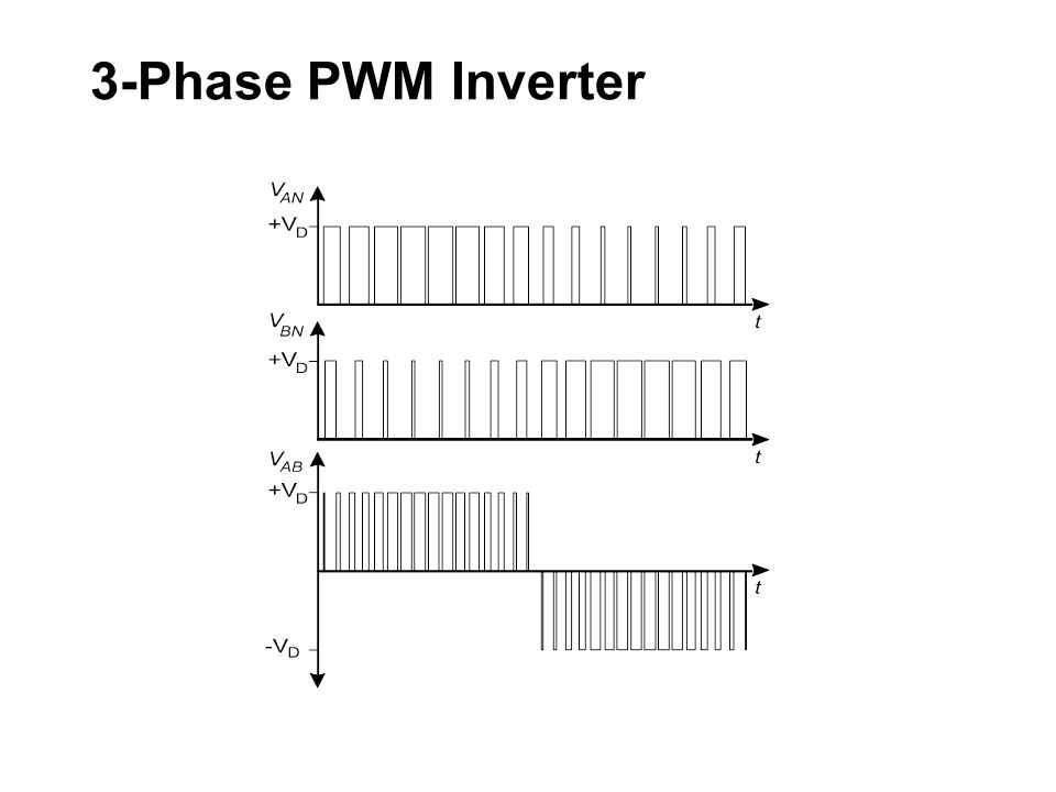
PWM Inverter X Output Frequency controlled... by changing switching speed X Output Voltage controlled... by changing the Pulse Width X Output Current waveform … depends on load impedance

48
Synthesized AC Waveform-PWM

49
PWM Inverter

50
X Modulation Technique for sine-coded PWM using the Sine- Triangle intersection method - digital implementation PWM Inverter

51
3-Phase PWM Inverter

53
AC Variable speed drives X In general, AC Variable Speed Drives are designed to... l Transform Electrical Energy into rotational Mechanical Energy X In most applications... l Control Speed with reasonable accuracy X In special Applications... l Need accurate and fast dynamic control of speed and torque

54
There are 3 basic types of AC Variable Speed Drive available today X “Standard” Fixed V/f Drive (also known as a VVVF Drive) … l OK for Pumps & Fans l Less expensive than the devices below X Sensorless Vector Control Drive … l Better Speed Regulation l Better Starting Torque & Acceleration X Field Oriented Flux Vector Control Drive... l Full implementation of Vector Control Strategy l Excellent Speed and Torque control characteristics AC Variable speed drives

55
Variable speed drive control loops The Level of Control can be... X Simple Open-Loop Control... l This is the strategy used for Fixed V/f drives l No internal feedback from the motor (except for protection) X Closed-Loop Control... l This is the strategy used for Vector Control drives l Feedback from the motor used to adjust PWM output l Achieves enhanced performance X Cascade Closed-Loop Control... l Strategy used for Field Oriented Flux Vector Control drives l Feedback of Torque and Speed used to improve dynamic performance l Achieves better than DC Drive performance
 X Closed-Loop Control... l This is the strategy used for Vector Control drives l Feedback from the motor used to adjust PWM output l Achieves enhanced performance X Cascade Closed-Loop Control... l Strategy used for Field Oriented Flux Vector Control drives l Feedback of Torque and Speed used to improve dynamic performance l Achieves better than DC Drive performance.")
56
Open loop control X Open loop speed control is suitable for.... l Applications where Speed Accuracy not important l Consequences of changes in the process not severe X Standard fixed V/f drives... are essentially Open Loop type

57
X Speed Reference fed to Ramp Circuit to convert step change in the speed request to a slowly changing signal X V/f Regulator sets magnitude of Voltage and Frequency X Finally, PWM Switching logic section controls the switches according to a PWM algorithm (sine-coded, etc) X No speed feedback from the motor.... open-loop control X Current feedback is for protection, indication & current limit Open loop control

58
X Closed Loop Control used for more difficult drive applications... l Torque, Speed or Position accurately controlled l Accuracy of control..... very important l Errors.... have a large influence on the process X For these applications, Closed Loop Control is necessary l Generally applies to high performance VSDs.... such as DC Drives and Vector controlled AC VSDs l Standard fixed V/f AC Drives can be used in closed loop systems... but they are not capable of high performance Closed loop control

59
X Accurate Feedback from motor transducer..... l Speed transducer …tacho or encoder l Position transducer …position encoder l Torque transducer …current transducer X Power Converter.... controls the Motor response X Controller.... which controls the Converter

60
X Closed Loop Control System operates as follows.... l Measurement of Process Variable (PV).... eg an encoder l Comparison of PV with Set Point (SP) gives an error value.... error value = SP - PV l Error value processed by Controller to adjust the Output, which in turn Controls the AC converter and motor X In industrial applications, the controller is a Microprocessor Closed loop control
.... eg an encoder l Comparison of PV with Set Point (SP) gives an error value.... error value = SP - PV l Error value processed by Controller to adjust the Output, which in turn Controls the AC converter and motor X In industrial applications, the controller is a Microprocessor Closed loop control.")
61
X Motor Car..... example of a closed-loop feedback control l Speed assessed by the driver looking at speedometer l Measured speed (PV) is compared to desired speed (SP) l Depending on the error, the driver may decide to increase speed by pressing the accelerator decrease speed by pressing the brake l Driver continually measures PV, calculates the error and gives the appropriate Output X At the same time, Driver might be simultaneously engaged in several other tasks of closed-loop feedback control, such as steering, controlling cabin temperature, etc. Closed loop control
 is compared to desired speed (SP) l Depending on the error, the driver may decide to increase speed by pressing the accelerator decrease speed by pressing the brake l Driver continually measures PV, calculates the error and gives the appropriate Output X At the same time, Driver might be simultaneously engaged in several other tasks of closed-loop feedback control, such as steering, controlling cabin temperature, etc. Closed loop control.")
62
Cascaded loop control X If each variable was proportional to the variable before it l Simple Open-loop control, without feedback would be OK l In a VSD.... some time delays not simply proportional... motor current responds to new frequency with a rise l The time is dependent on its leakage inductance l Motor speed follows the torque with a rise time... dependent on its inertia X Inaccuracies acceptable in simple applications.... l Speed control for pumps, conveyors, etc X Some applications require Close Speed and Torque control l Speed and Torque control of paper machine VSDs

63
X Design techniques have evolved from DC Drives... and deals with control problem in two smaller stages l Speed Loop compares speed... calculates current setpoint l Current Loop compares current... calculates frequency setpoint Cascaded loop control

64
X Speed Loop allows for one of time delays in system l delay between the torque and the measured speed X Current Loop allows for other time delay.... l delay between the output frequency and the current l rate of change of current is faster than change of speed X The two control loops required for accurate speed control are l An outer Speed Control Loop, which compensates for the mechanical transients, mainly load inertia l An inner Torque Control Loop, which compensates for the electrical transients, mainly winding X and R Cascaded loop control

65
Vector control X Vector Control... l Been available since the mid-1980s l Promoted as an AC equivalent to DC Drives l Only become possible as a result of the large strides in the fields of power electronics and digital control X Gets its name from the fact that.... l System can separately measure and control the two Vector components of the stator current l Vectors represent magnitude and direction of the current l Specifically....Flux current and Torque-producing current

66
X Vector Control is a “generic” name applied to all AC Drives that provide performance that is higher than “standard” AC Drives X Vector Control is one of the more abused terms used to promote the use of modern AC Variable Speed Drives... l performance said to be equivalent to high performance DC Drives X Dynamic Performance that is equivalent to a DC Drive is only possible if Vector Control is fully implemented l There are many Vector Control Drives on the market that only partially implement the strategy Vector control

67
X Simplified equivalent circuit of an AC Induction Motor X Using a Hall-effect current transducer, the drive can measure the Stator Current I S flowing to the motor... but NOT I R and I M Vector control

68
X I R and I M are the Vector components of Current I S X Vector components can be calculated from measured values Vector control

69
X Therefore, the main purpose of Vector controller is to... l Continuously calculate value of Flux Current I M l Continuously calculate value of Torque Producing Current I R l Continuously calculate other variables such as Slip, Shaft Speed, etc X Central part of Vector control is the Active Motor Model... l Uses motor constants stored in memory as part of calculation to continuously model the connected motor l Measures stator current in each phase and uses this to calculate the torque current (I R ) and flux current (I M ) l Measures actual speed and calculates slip l For adequate dynamic response of the drive, these calculations need to be done at a rate of more than 2,000 times per sec l This only became commercially viable within last 10 years with development of 16-bit microprocessors Vector control
 and flux current (I M ) l Measures actual speed and calculates slip l For adequate dynamic response of the drive, these calculations need to be done at a rate of more than 2,000 times per sec l This only became commercially viable within last 10 years with development of 16-bit microprocessors Vector control.")
70
X These are essentially Fixed V/f “open loop” drives with some performance enhancements due to a digital “Motor Model” X The Motor Model is used to calculate 2 main variables l Flux Current (I M )... to automatically regulate output V/f ratio. This results in improved Torque performance, particularly at low speeds l Percentage Slip... to automatically regulate output frequency. This results in improved Speed holding performance... without the need for a shaft mounted encoder (hence the name Sensorless Vector Control) X For Sensorless Vector Control to be effective, the drive needs to be “tuned” to the connected motor l Auto-tuning feature normally available... used to measure the required motor parameters and store them in memory Sensorless vector control
 X For Sensorless Vector Control to be effective, the drive needs to be tuned to the connected motor l Auto-tuning feature normally available... used to measure the required motor parameters and store them in memory Sensorless vector control.")
71
Field oriented flux vector drives X These are ”Closed loop” drives with an Active Motor Model and cascaded Speed and Torque control loops X The high performance microprocessor runs a Motor Model that can calculate numerous drive variables X For the Vector Control to be effective, the drive needs to be “tuned” to the connected motor l Auto-tuning feature normally available... used to measure the required motor parameters and store them in memory X Field Oriented Flux-Vector Control necessary on drives where... l Accurate speed and/or torque control is necessary l High dynamic performance is required... speeds and/or load torque change rapidly l Full torque is required at zero speed... for example on hoists

72
X In a Flux Vector drive... l The Power circuit is identical to fixed V/f drive l Main difference...... is in the control system Field oriented flux vector drives

73
X Flux-Vector control of a PWM Converter.... l Control is essentially Cascaded Closed-loop type Field oriented flux vector drives

74
Vector control performance Some interesting Figures …

75
Basic setting parameters X Remaining Parameters settings can be selected as follows : l Maximum speed... usually set to 50Hz or higher l Minimum speed... usually 0Hz for a pump or fan drive and higher for constant torque applications l Rated Motor Current... size of motor may be small l Current Limit... determines Starting Torque l Acceleration Time... determines the Ramp-up Time l Deceleration Time... determines the Ramp-down Time l Braking Method... 3 Options usually available l Starting Torque Boost... cover Breakaway Torque Note : Avoid over-fluxing the motor !!! X Other Settings... possibly adjust "default" settings

76
Synthesizing an AC Wave- Examples X Simple square wave X Square wave with smaller conduction width X Trapezoidal waveform X A series of pulses of fixed amplitude but varying width within a cycle (known as pulse width modulation or PWM)
")
77
Protection of AC variable speed drives X The protection of AC Variable Speed Drives includes... l Protection of the AC Converter l Protection of the Electric Motor

78
AC Converter protection X Protection for front-end rectifier usually NOT provided … l Usually require external upstream short-circuit protection l HRC fuses or fast Circuit Breaker X Following protection usually included... l Protection systems for the PWM Inverter l Protection for DC Busbar l Protection for Output … Motor and Motor Cable Motor thermal overload protection Motor short circuit protection Motor earth fault protection

79
Summary of overall protection

80
Input phase imbalance X One input phase voltage low.... l Other 2 phases will conduct majority of supply current l Possible failure of rectifier diodes X DC Current... miss every 3rd pulse, other 2 pulses higher l can lead to failure of the rectifier diodes or capacitors X Input Phase Imbalance Protection implemented by..... l Measuring the Input Currents.... Costly l Monitoring the DC bus.... analyse waveform distortion

81
DC bus under voltage X Power Circuit can operate at any voltage 0 - V Max X Under-voltage protection required for Power Supplies l Typically set to 15% below lowest rated voltage X When Power Supply output voltage regulation is lost... l Microprocessor could switch to an indeterminate state l Driver circuits lose control of the Power Switches l Power Switch may attempt to operate in the linear region l Power Switch may be slow to switch off l Power Electronic Switches will fail

82
DC bus over voltage X All electrical components fail if exposed to high Over-voltage X In AC drives, high DC over-voltages can occur due to... l High voltages in the mains power supply... Very Rare l Motor behaving as Induction Generator.... dynamic braking of a high inertia load X The following components have the lowest tolerances to High Voltages.... l DC bus Capacitor Bank l DC bus connected Power Supply Modules l Power Electronic Switching Devices

83
X DC capacitor bank... series and parallel capacitors l Sharing will not be perfect X Peak voltage on DC bus is approx 1.4 x supply voltage l With a maximum capacitor voltage of V Max = 750VDC... the practical limit for input voltage is 480VAC + 10% l For AC drives with >500Volt input, special capacitors are required X Maximum voltage of Semiconductor switches is 1,400 VDC l Seems well above Capacitor rating l But, voltage across a device during turn-off can be l 400V higher, due to stray circuit inductances l Bus voltage must be limited to 800 VDC Maximum DC bus over voltage

84
X In Modern Digital AC drives... l Over-voltage Protection provided by microprocessor because DC bus voltage changes relatively slowly X Digital controller can also provide over-voltage control l During deceleration of load... override ramp-down setting to prevent the over-voltage trip l DC bus voltage allowed to rise to safe 750 VDC l Trip level typically at 800 VDC DC bus over voltage

85
Operation interface & diagnostics X Human Interface Module (HIM).... LCD or LED Display X 3 Main levels of operator information and fault diagnostics : 1.Parameters... Settings, Status and Metering 2.Diagnostic information... Status of Protection Circuits 3.Diagnostic information... Status of Internal Circuits... internal diagnostics only found in special VSDs

86
Internal parameters X Typical Internal Parameters and Fault Diagnostics...

87
Fault diagnostics - parameters X Common Faults... possible Internal/External Problems

88
Motor side filter X Connection Example of Line Filter and Motor Filter

89
Natural ventilation X Enclosure can be Smaller... additional Ventilation required l Exchange air between Inside and Outside of enclosure X Natural Ventilation l Convectional cooling airflow through air vents l Vents at Bottom and Top..... the "chimney" effect

90
Forced ventilation X Cooling airflow assisted by fan at Top or Bottom of cubicle

91
General safety requirements X Requirements for Safety.... should be carefully followed l Australian Standard AS 3000 : SAA Wiring Rules apply l Safety earths must be installed before power connected X AC Converters have Large Capacitors on the DC link l After VSD switched off..... wait several minutes l Allow internal capacitors to fully discharge l Visual Indication... shows when capacitors are charged

92
Hazardous areas X AC Converters should NOT be mounted in Hazardous Areas..... even when connected to an Ex rated motor X When necessary..... l AC converters may be mounted in Approved Enclosure l Certification should be obtained for entire VSD System.... including both Converter and Motor

93
Any questions ?

Similar presentations
>")


>")


900-2220. PSI Pump Systems Inc. 1(800)900-2220 Variable Frequency Drives Presented by PSI Pump Systems Inc. “ Your Solutions.>")


