Download presentation
Presentation is loading. Please wait.

1
Rapid Prototyping

2
Definition Rapid Prototyping (RP) can be defined as a group of techniques used to quickly fabricate a scale model of a part or assembly using three-dimensional computer aided design (CAD) data.
 can be defined as a group of techniques used to quickly fabricate a scale model of a part or assembly using three-dimensional computer aided design (CAD) data.")
3
Why Rapid Prototyping?(1 of 2)
The reasons of Rapid Prototyping are To increase effective communication. To decrease development time. To decrease costly mistakes. To minimize sustaining engineering changes. To extend product lifetime by adding necessary features and eliminating redundant features early in the design.

4
Why Rapid Prototyping? (2 of 2)
Rapid Prototyping decreases development time by allowing corrections to a product to be made early in the process. By giving engineering, manufacturing, marketing, and purchasing a look at the product early in the design process, mistakes can be corrected and changes can be made while they are still inexpensive. The trends in manufacturing industries continue to emphasize the following: Increasing number of variants of products. Increasing product complexity. Decreasing product lifetime before obsolescence. Decreasing delivery time. Rapid Prototyping improves product development by enabling better communication in a concurrent engineering environment.

5
Methodology of Rapid Prototyping
The basic methodology for all current rapid prototyping techniques can be summarized as follows: 1.A CAD model is constructed, then converted to STL format. The resolution can be set to minimize stair stepping. 2.The RP machine processes the .STL file by creating sliced layers of the model. 3.The first layer of the physical model is created. The model is then lowered by the thickness of the next layer, and the process is repeated until completion of the model. 4.The model and any supports are removed. The surface of the model is then finished and cleaned.

6
Types of Rapid Prototyping
Stereolithography (SLA) Selective Laser Sintering (SLS®) Laminated Object Manufacturing (LOM™) Fused Deposition Modeling (FDM) Solid Ground Curing (SGC) Ink Jet printing
 Selective Laser Sintering (SLS®) Laminated Object Manufacturing (LOM™) Fused Deposition Modeling (FDM) Solid Ground Curing (SGC) Ink Jet printing.")
7
Stereolithography Stereolithography (SLA), the first Rapid Prototyping process, was developed by 3D Systems of Valencia, California, USA, founded in A vat of photosensitive resin contains a vertically-moving platform. The part under construction is supported by the platform that moves downward by a layer thickness (typically about 0.1 mm / inches) for each layer. A laser beam traces out the shape of each layer and hardens the photosensitive resin.
, the first Rapid Prototyping process, was developed by 3D Systems of Valencia, California, USA, founded in A vat of photosensitive resin contains a vertically-moving platform. The part under construction is supported by the platform that moves downward by a layer thickness (typically about 0.1 mm / inches) for each layer. A laser beam traces out the shape of each layer and hardens the photosensitive resin.")
8
The Stereolithography (SLA) System overall arrangement:
 System overall arrangement:")
9
3D Systems Viper™ SLA system

10
Selective Laser Sintering (SLS®)
Selective Laser Sintering (SLS®, registered trademark by DTM™ of Austin, Texas, USA) is a process that was patented in 1989 by Carl Deckard, a University of Texas graduate student. Its chief advantages over Stereolithography (SLA) revolve around material properties. Many varying materials are possible and these materials can approximate the properties of thermoplastics such as polycarbonate, nylon, or glass-filled nylon.
 is a process that was patented in 1989 by Carl Deckard, a University of Texas graduate student. Its chief advantages over Stereolithography (SLA) revolve around material properties. Many varying materials are possible and these materials can approximate the properties of thermoplastics such as polycarbonate, nylon, or glass-filled nylon.")
11
As the figure below shows, an SLS® machine consists of two powder magazines on either side of the work area. The leveling roller moves powder over from one magazine, crossing over the work area to the other magazine. The laser then traces out the layer. The work platform moves down by the thickness of one layer and the roller then moves in the opposite direction. The process repeats until the part is complete.

12
SLA vs. SLS: A Summarized Comparison
Material Properties: The SLA (stereolithography) process is limited to photosensitive resins which are typically brittle. The SLS® process can utilize polymer powders that, when sintered, approximate thermoplastics quite well. Surface Finish: The surface of an SLS® part is powdery, like the base material whose particles are fused together without complete melting. The smoother surface of an SLA part typically wins over SLS® when an appearance model is desired. In addition, if the temperature of uncured SLS® powder gets too high, excess fused material can collect on the part surface. This can be difficult to control since there are so many variables in the SLS® process. In general, SLA is a better process where fine, accurate detail is required. However, a varnish-like coating can be applied to SLS® parts to seal and strengthen them. Machining Properties: In general, SLA materials are brittle and difficult to machine. SLS® thermoplastic-like materials are easily machined.
 process is limited to photosensitive resins which are typically brittle. The SLS® process can utilize polymer powders that, when sintered, approximate thermoplastics quite well. Surface Finish: The surface of an SLS® part is powdery, like the base material whose particles are fused together without complete melting. The smoother surface of an SLA part typically wins over SLS® when an appearance model is desired. In addition, if the temperature of uncured SLS® powder gets too high, excess fused material can collect on the part surface. This can be difficult to control since there are so many variables in the SLS® process. In general, SLA is a better process where fine, accurate detail is required. However, a varnish-like coating can be applied to SLS® parts to seal and strengthen them. Machining Properties: In general, SLA materials are brittle and difficult to machine. SLS® thermoplastic-like materials are easily machined.")
13
3D Systems Sinterstation® HiQ™ Series SLS® System

14
Laminated Object Manufacturing (LOM™)
Layers of glue-backed paper form the model. Low cost: Raw material is readily available. Large parts: Because there is no chemical reaction involved, parts can be made quite large. Accuracy in z is less than that for SLA and SLS®. No milling step. Outside of model, cross-hatching removes material Models should be sealed in order to prohibit moisture. Before sealing, models have a wood-like texture. Not as prevalent as SLA and SLS®.

15
The figure below shows the general arrangement of a Laminated Object Manufacturing (LOM™, registered trademark by Helisys of Torrance, California, USA) cell:
 cell:")
16
Material is usually a paper sheet laminated with adhesive on one side, but plastic and metal laminates are appearing. 1.Layer fabrication starts with sheet being adhered to substrate with the heated roller. 2.The laser then traces out the outline of the layer. 3.Non-part areas are cross-hatched to facilitate removal of waste material. 4.Once the laser cutting is complete, the platform moves down and out of the way so that fresh sheet material can be rolled into position. 5.Once new material is in position, the platform moves back up to one layer below its previous position. 6.The process can now be repeated.

17
Cubic Technologies Laminated Object Manufacturing

18
Fused Deposition Modeling (FDM)
Standard engineering thermoplastics, such as ABS, can be used to produce structurally functional models. Two build materials can be used, and latticework interiors are an option. Parts up to 600 × 600 × 500 mm (24 × 24 × 20 inches) can be produced. Filament of heated thermoplastic polymer is squeezed out like toothpaste from a tube. Thermoplastic is cooled rapidly since the platform is maintained at a lower temperature. Milling step not included and layer deposition is sometimes non-uniform so "plane" can become skewed. Not as prevalent as SLA and SLS®, but gaining ground because of the desirable material properties.
 can be produced. Filament of heated thermoplastic polymer is squeezed out like toothpaste from a tube. Thermoplastic is cooled rapidly since the platform is maintained at a lower temperature. Milling step not included and layer deposition is sometimes non-uniform so plane can become skewed. Not as prevalent as SLA and SLS®, but gaining ground because of the desirable material properties.")
19
Stratasys of Eden Prairie, MN makes Fused Deposition Modeling (FDM) machines. The FDM process was developed by Scott Crump in The fundamental process involves heating a filament of thermoplastic polymer and squeezing it out like toothpaste from a tube to form the RP layers. The machines range from fast concept modelers to slower, high-precision machines. The materials include polyester, ABS, elastomers, and investment casting wax. The overall arrangement is illustrated

20
Fused Deposition Modeling

21
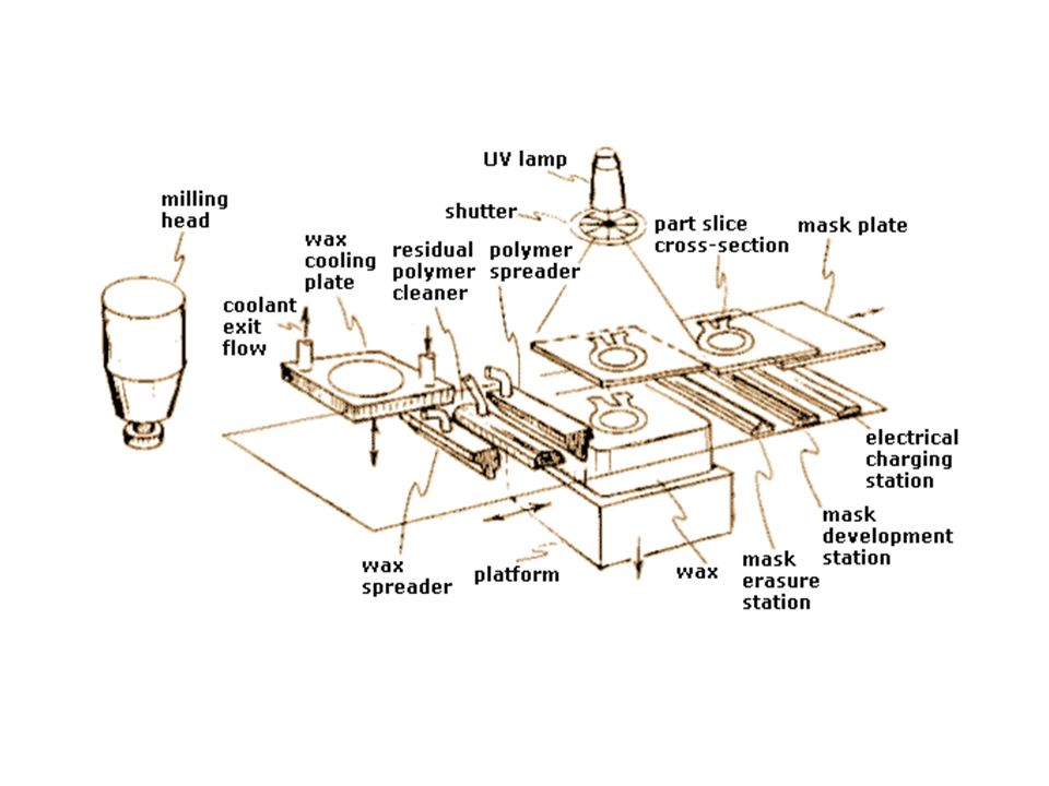
Solid Ground Curing (SGC)
Solid Ground Curing, also known as the Solider Process, is a process that was invented and developed by Cubital Inc. of Israel. The overall process is illustrated in the figure above and the steps are illustrated below. The SGC process uses photosensitive resin hardened in layers as with the Stereolithography (SLA) process. However, in contrast to SLA, the SGC process is considered a high-throughput production process. The high throughput is achieved by hardening each layer of photosensitive resin at once. Many parts can be created at once because of the large work space and the fact that a milling step maintains vertical accuracy. The multi-part capability also allows quite large single parts (e.g. 500 × 500 × 350 mm / 20 × 20 × 14 in) to be fabricated. Wax replaces liquid resin in non-part areas with each layer so that model support is ensured.
 process. However, in contrast to SLA, the SGC process is considered a high-throughput production process. The high throughput is achieved by hardening each layer of photosensitive resin at once. Many parts can be created at once because of the large work space and the fact that a milling step maintains vertical accuracy. The multi-part capability also allows quite large single parts (e.g. 500 × 500 × 350 mm / 20 × 20 × 14 in) to be fabricated. Wax replaces liquid resin in non-part areas with each layer so that model support is ensured.")
23
Ink Jet printing RP ink jet techniques utilize ink jet technology to shoot droplets of liquid-to-solid compound and form a layer of an RP model. Common ink jet printing techniques, such as Sanders ModelMaker™, Multi-Jet Modeling™, Z402 Ink Jet System™, and Three-Dimensional Printing, are presented in this section. Although none of the these techniques have become as established as the Stereolithography (SLA) or Selective Laser Sintering (SLS®) systems, several show promise.
 or Selective Laser Sintering (SLS®) systems, several show promise.")
25
Rapid Prototyping Machines Stereolithography (SLA), Selective Laser Sintering (SLS®), Laminated Object Manufacturing (LOM™), Fused Deposition Modeling (FDM), Solid Ground Curing (SGC) 45 thousand dollars or more Free standing More to clean up Can create objects up to 3 feet cubed Material can cost over 40 thousand dollars per year Wider range of materials can be used More precise and can create more intricate patterns Takes longer than a 3D printer to create a product

26
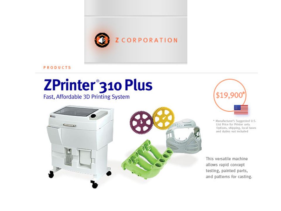
3-D Printing Machines Ink Jet printing
Lower in cost 10-15 thousand dollars Could be placed on a table Less clean up Only creates small objects Less that 10 inches cubed Less material cost than Rapid Prototyping Few materials the printer can use Small amount of first time use training Creates products much faster

27
Resources All information was taken from the following website:
Similar presentations


>")
Thermoplastics, metal powders Fused deposition modeling (FDM)Thermoplastics,>")


 drawing. With the use.>")


