Download presentation
Presentation is loading. Please wait.

1
James Holloway & Muhammad F. Kasim University of Oxford, UK PhD Supervisors: Professor Peter Norreys & Professor Philip Burrows University of Oxford, UK AWAKE Meeting, Geneva, 18 November 2015 Plasma Wakefield Diagnostics in AWAKE

2
AWAKE Collaboration Meeting, 28 – 30 September 2015 2 University of Oxford, RAL, UCL Parameters

3
AWAKE Collaboration Meeting, 28 – 30 September 2015 3 University of Oxford, RAL, UCL Spectrograph on the shelf: –Supplier: Princeton Instruments –Type: Czerny-Turner –Focal length: 75 cm (SP-2750) –Gratings: 2400 g/mm Detector on the shelf: –Supplier: Thorlabs –CCD pixel size: 7.4 –CCD resolution: 2048 x 2048 Detector parameters: –Central wavelength: 390 nm –Wavelength range: ~ 8.3 nm –Wavelength resolution: ~ 0.01 nm –Pixel resolution: ~0.003 nm Parameters
 –Gratings: 2400 g/mm Detector on the shelf: –Supplier: Thorlabs –CCD pixel size: 7.4 –CCD resolution: 2048 x 2048 Detector parameters: –Central wavelength: 390 nm –Wavelength range: ~ 8.3 nm –Wavelength resolution: ~ 0.01 nm –Pixel resolution: ~0.003 nm Parameters")
4
AWAKE Collaboration Meeting, 28 – 30 September 2015 4 University of Oxford, RAL, UCL Laser room

5
AWAKE Collaboration Meeting, 28 – 30 September 2015 5 University of Oxford, RAL, UCL Beam height: Laser room

6
AWAKE Collaboration Meeting, 28 – 30 September 2015 6 University of Oxford, RAL, UCL Laser pipe transport in the tunnel: Laser room

7
AWAKE Collaboration Meeting, 28 – 30 September 2015 7 University of Oxford, RAL, UCL Laser pick-off

8
AWAKE Collaboration Meeting, 28 – 30 September 2015 8 University of Oxford, RAL, UCL One side pick-off Laser pick-off Focused field 1D slice profiles ~7%

9
AWAKE Collaboration Meeting, 28 – 30 September 2015 9 University of Oxford, RAL, UCL Round pick-off Laser pick-off Focused field 1D slice profiles ~9%

10
AWAKE Collaboration Meeting, 28 – 30 September 2015 10 University of Oxford, RAL, UCL Laser transport (upstream)
")
11
AWAKE Collaboration Meeting, 28 – 30 September 2015 11 University of Oxford, RAL, UCL Laser transport (upstream)
")
12
AWAKE Collaboration Meeting, 28 – 30 September 2015 12 University of Oxford, RAL, UCL Laser transport (upstream)
")
13
AWAKE Collaboration Meeting, 28 – 30 September 2015 13 University of Oxford, RAL, UCL Laser transport (upstream)
")
14
AWAKE Collaboration Meeting, 28 – 30 September 2015 14 University of Oxford, RAL, UCL Laser transport (upstream)
")
15
AWAKE Collaboration Meeting, 28 – 30 September 2015 15 University of Oxford, RAL, UCL Laser transport (upstream)
")
16
AWAKE Collaboration Meeting, 28 – 30 September 2015 16 University of Oxford, RAL, UCL Plasma wakefield diagnostics working region (including some blockings due to geometry): AWAKE Working Region (2.5 – 5) m
: AWAKE Working Region (2.5 – 5) m")
17
3D model courtesy of Ans Pardons Proposed merge point: A Require 15 cm long box with window in which to mount a 1 inch mirror

18
3D model courtesy of Ans Pardons Require 15 cm long box with window in which to mount a 1 inch mirror Proposed merge point: B

19
3D model courtesy of Ans Pardons Require 15 cm long box with window in which to mount a 1 inch mirror Incorporate probe merge point and vacuum gauge? Proposed merge point: C Vacuum gauge

20
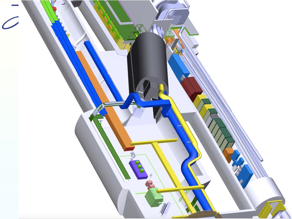
ADL abandoned. Now have expansion volume Adds 50 cm to each end. ? ?

21
Expansion volume has 2 mm of rubidium build up every two weeks ? ? ADL abandoned. Now have expansion volume

22
Adds 50 cm to each end. Expansion volume has 2 mm of rubidium build up every two weeks Cannot put components inside ? ? ADL abandoned. Now have expansion volume

23
Into the plasma cell OUTDATED Acoustic Delay Line restricted space for probe laser pulse Probe beam is 10 mm, entrance and exit window was to be 10 mm No room for manover Entrance Acoustis delay line Sapphire glass Probe Window (ideal case) 10 mm 20 mm
 10 mm 20 mm")
24
Sapphire window ? ? Need to pass probe into plasma stage Without ADL, there is space for 15 mm window This increases probable wakefield region

25
? ? Sapphire window Need to pass probe into plasma stage Without ADL, there is space for 15 mm window This increases probable wakefield region

26
? ? Sapphire window in plate Sapphire window – port Need to pass probe into plasma stage Without ADL, there is space for 15 mm window This increases probable wakefield region 20 mm

27
? ? Sapphire window in plate Sapphire window – port Need to pass probe into plasma stage Without ADL, there is space for 15 mm window This increases probable wakefield region Entrance Probe Window (ideal case) 10 mm 15 mm Note, no rubidium deposit on window because sapphire is above condensation temperature (~ 23 C)
 10 mm 15 mm Note, no rubidium deposit on window because sapphire is above condensation temperature (~ 23 C)")
28
Entrance Sapphire plate Sapphire window – plate 10 mm Sapphire Whole face of plasma cell is sapphire window Provides maximum flexibility for probing regions of plasma Angle and translation Note, no rubidium deposit on window because sapphire is above condensation temperature (~ 23 C)
")
29
Entrance Sapphire plate Sapphire window – plate 10 mm Sapphire Whole face of plasma cell is sapphire window Provides maximum flexibility for probing regions of plasma Angle and translation Note, no rubidium deposit on window because sapphire is above condensation temperature (~ 23 C)
")
30
Sapphire properties Melting point ~ 2,000 C It will have to width stand ~ 200 C Strong Approximate pressure of plasma on window will be 1 Pa (10 -5 bar ) This gives a force of one newton for a window of O(10 mm 2 ) this Inert From our findings so far it should not react with the rubidium Commonly used well known and existing manufacturers produce to optical standards Can test on ‘dirty’ plasma stage
 This gives a force of one newton for a window of O(10 mm 2 ) this Inert From our findings so far it should not react with the rubidium Commonly used well known and existing manufacturers produce to optical standards Can test on ‘dirty’ plasma stage")
31
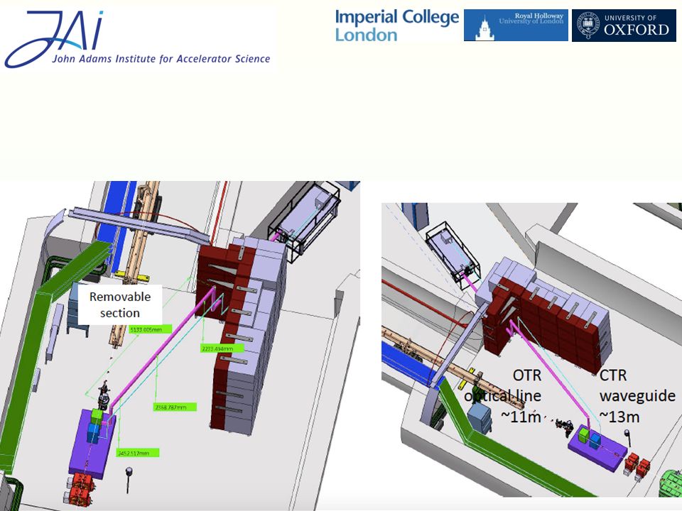
3D model courtesy of Ans Pardons Diagnostic table Interested in this area Need ~ 1 m 2 for spectrometer and accompanying optics Optical fibre not possible Ideally add an additional optical line! Alternatively use mirrors to pass onto diagnostic table the long way

32
3D model courtesy of Ans Pardons Diagnostic table Interested in this area Need ~ 1 m 2 for spectrometer and accompanying optics Optical fibre not possible Ideally add an additional optical line! Alternatively use mirrors to pass onto diagnostic table the long way

33
Data Acquisition Acquiring optics on each shot: Two Auto alignment cameras One transverse beam profile One Andor 2048 x 2048 Approximately 20 mb for each shot. 40 mb after backing up. For a run of 1000 shots that is very little (40 gb). Data recorded in one of two ways: Locally on machines in the experimental area and copied across to control room Or straight to control room. Gigabit ethernet interface will suffice. Intend to have a machine in the experimental area for Auto alignment system
. Data recorded in one of two ways: Locally on machines in the experimental area and copied across to control room Or straight to control room. Gigabit ethernet interface will suffice. Intend to have a machine in the experimental area for Auto alignment system.")
34
Auto alignment system AA system components purchased Implementing on Muhammad’s 3D spectrometer to test in situ Alleviates concerns about pointing of our probe pulse (need sub 1 mrad precision)
")
35
Safety Going through a fire door? Height of probe pulse in laser room Working with 800nm and 400nm lasers in same area (opaque goggles) Shielding of probe pulse beam line (so far considered simple beam block) Safety issues from your side?
 Shielding of probe pulse beam line (so far considered simple beam block) Safety issues from your side .")
36
Summary Probe pulse can be generated from 50 mJ pick off of ionisation beam Merging requires space! (Sapphire) window is mission critical for the diagnostic Need large space for forward diagnostic table DAQ system is simple Racks / cabling needs to be discussed in future Safety concerns are not major but need to be addressed
 window is mission critical for the diagnostic Need large space for forward diagnostic table DAQ system is simple Racks / cabling needs to be discussed in future Safety concerns are not major but need to be addressed.")
37
Generating The Probe Beam Pick off (a small piece!) from ionisation laser before compression Frequency double Issues No space in laser room Minimal spare energy in ionisation laser pulse Solution Small bread board (dimensions) above will have beam X cm below head height. If zero energy spare – run diagnostic when photo injector not running (phase I when most useful) If little energy spare – no problem! 50 TW cm -2 for ionising pulse. Need 2 TWcm -2 ionize. 3D model courtesy of Ans Pardons ? ?
 If little energy spare – no problem. 50 TW cm -2 for ionising pulse. Need 2 TWcm -2 ionize. 3D model courtesy of Ans Pardons . .")
38
Generating The Probe Beam Pick off (a small piece!) from ionisation laser before compression Frequency double Issues No space in laser room Minimal spare energy in ionisation laser pulse Solution Small bread board (dimensions) above will have beam X cm below head height. If zero energy spare – run diagnostic when photo injector not running (phase I when most useful) If little energy spare – no problem! 50 TW cm -2 for ionising pulse. Need 2 TWcm -2 ionize. 3D model courtesy of Ans Pardons
 If little energy spare – no problem. 50 TW cm -2 for ionising pulse. Need 2 TWcm -2 ionize. 3D model courtesy of Ans Pardons.")
39
Probe beam: From Laser room to plasma cell Probe uses same transport mirrors as ionisation laser – probe beam offset The probe pulse is ‘caught’ by a small mirror before entering the plasma cell Plasma Cell Ionising laser Probe laser

40
Probe beam: From Laser room to plasma cell Issues Auto alignment system (if implemented?) Clipping Solution Frequency doubled leaked probe pulse can be discriminated against with filters / dielectric mirrors etc Ionising laser Probe laser Leaky mirror Filter AA CCD
 Clipping Solution Frequency doubled leaked probe pulse can be discriminated against with filters / dielectric mirrors etc Ionising laser Probe laser Leaky mirror Filter AA CCD")
41
Probe beam: From Laser room to plasma cell Probe uses same transport mirrors as ionisation laser – probe beam overlaid Issues Ionisation pulse has two additional reflections (one dielectric mirror) More space required Plasma Cell Ionising laser Probe laser Dielectric
 More space required Plasma Cell Ionising laser Probe laser Dielectric")
42
3D model courtesy of Ans Pardons Probe beam: From Laser room to plasma cell Finalized design: crowed! Problem ? ? Solution: work with technical board and beg a shoebox of volume

43
The plasma cell Propagate probe pulse at a small angle (1 mrad) to proton beam axis Plasma cell has no window access Plasma cell has Ø = 40 mm Probe pulse has Ø = 10 mm Entrance Image pilfered from P. Muggli Acoutis delay line Sapphire glass Probe Window (ideal case)
.")
44
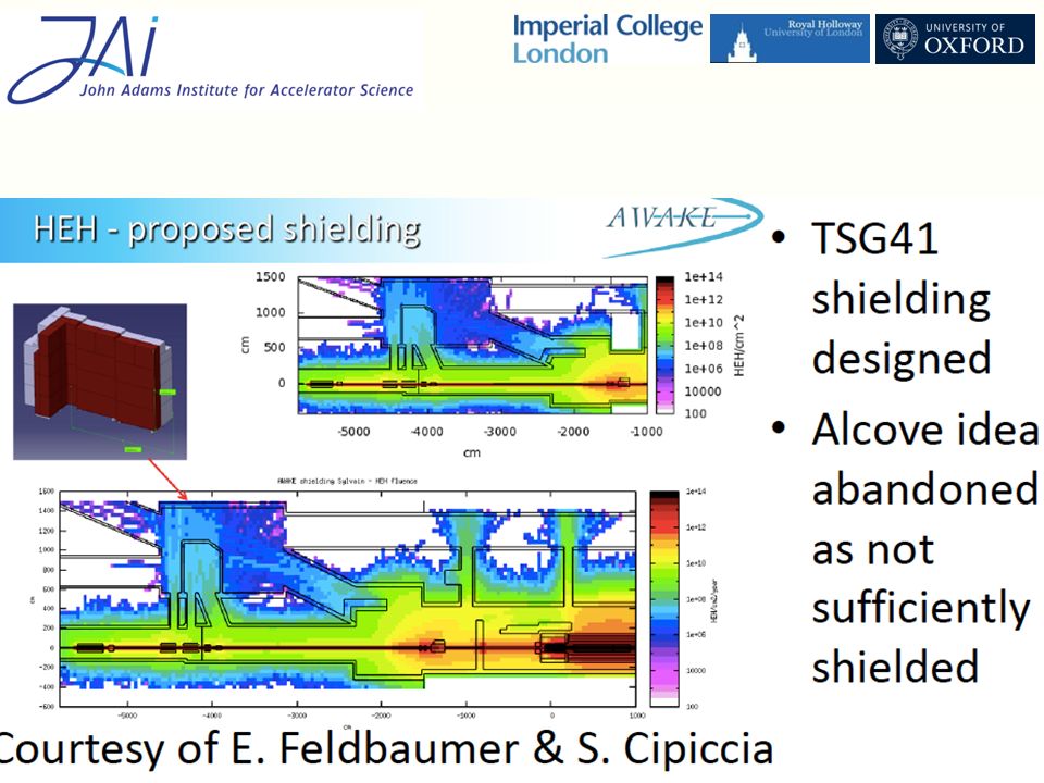
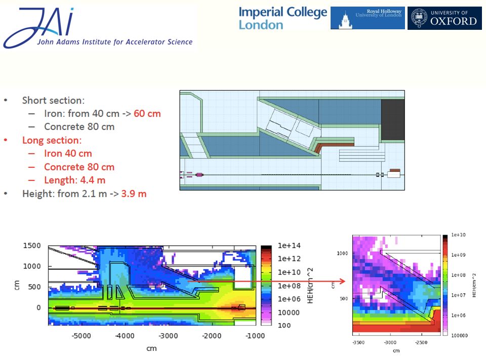
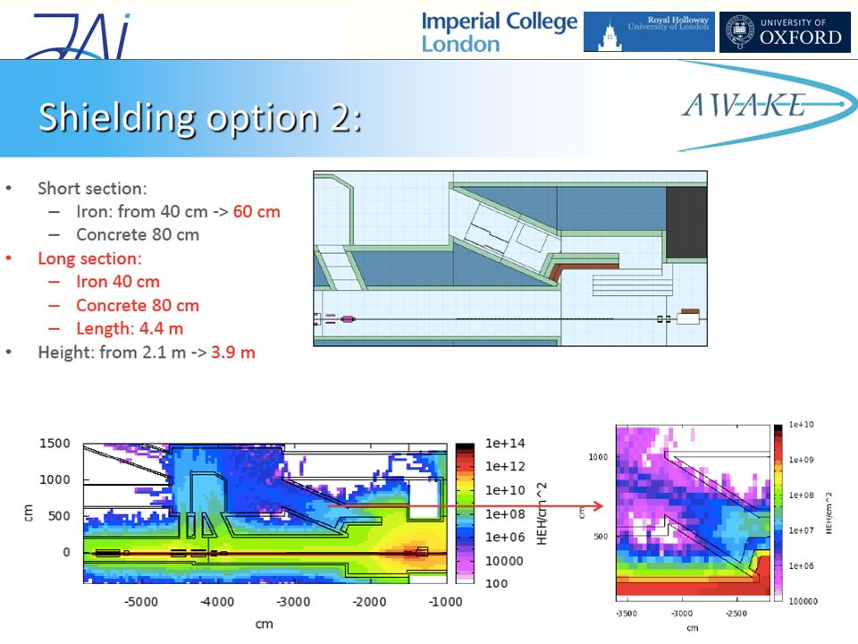
From plasma cell to diagnostic table There is not much space Radiation is an issue COTS systems limit: 1e+8 HEHcm -2 Courtesy of E. Feldbaumer and S. Cipiccia

45
Astra Experiment A 12 week experiment using the E = 500 mJ, T = 40 fs Astra laser pulse to drive a wakefield Test the diagnostic in situ Develop software to analyse data on the fly – real time plasma diagnostic Begins in May 2016

46
Thank you for listening

47
AWAKE Collaboration Meeting, 28 – 30 September 2015 47 University of Oxford, RAL, UCL Astra laser Single Beam Titanium Sapphire laser system 10 TW optical pulse at 10Hz / 25TW at 1Hz Experiments in Laser-Plasma Physics

54
A B C Probe beamline denoted by orange line. Key areas of photon acceleration diagnostic beamline denoted by A, B and C labels. Discussed in following slides. Probe beam diagnostic beamline: costing the auto-alignment system.

55
1)Probe laser picked off from ionising laser before final compression. Probe laser is T = 160 ps, 20 nm bandwidth NIR at this point. 2)Probe laser telescoped up to 10 mm diameter and frequency doubled using SHG crystal. Bandpass filter used to resulting in a 390 nm, 3 nm bandwidth, 26 ps duration probe laser pulse. Both 1) and 2) can be achieved on additional breadboard in laser room. 3)Probe laser passed from laser room to proton tunnel via r = 25 cm canal. Approximately 5 turning mirrors used over 5m to take from breadboard to proton tunnel. A: Laser Room.
Probe laser telescoped up to 10 mm diameter and frequency doubled using SHG crystal. Bandpass filter used to resulting in a 390 nm, 3 nm bandwidth, 26 ps duration probe laser pulse. Both 1) and 2) can be achieved on additional breadboard in laser room. 3)Probe laser passed from laser room to proton tunnel via r = 25 cm canal. Approximately 5 turning mirrors used over 5m to take from breadboard to proton tunnel. A: Laser Room..")
56
Probe laser steered in air down proton tunnel. Probe laser merged with proton and ionising laser pulse 2 m from plasma cell. Dog-leg used to pass through junction (non- critical). Probe laser merged with proton and ionising laser pulse 2 m from plasma cell. Pointing stability from the last mirror before plasma stage needs to be a maximum of 0.2 mrad, ideally 0.1 mrad. Distance from canal to start of plasma cell approximately 20 m. B: Proton Tunnel.
. Probe laser merged with proton and ionising laser pulse 2 m from plasma cell. Pointing stability from the last mirror before plasma stage needs to be a maximum of 0.2 mrad, ideally 0.1 mrad. Distance from canal to start of plasma cell approximately 20 m. B: Proton Tunnel..")
57
C: After Plasma Probe pulse has 1.5 m of propagation after plasma cell before entering diagnostic table breadboard (conceptual schematic below). ‘Variable path delay’ not significant compared to length of beamline. Note: The angle between the probe pulse and the proton beam is important to know on a shot-by-shot basis for analysis later. Would an auto alignment system have a feature where it could record such information?

58
? ? Adds 50 cm to each end. Expansion volume has 2 mm of rubidium build up every two weeks Cannot put components inside Expansion vol ADL abandoned. Now have expansion volume

Similar presentations


 2.Gas Chamber 3.Injection Chamber 4.Compressor 5.Transport (B) M. Litos July 24,>")


 No new information.>")


