Download presentation
Presentation is loading. Please wait.

1
Lecture 14 22/10/15

2
The Object-Oriented Analysis and Design Process of progressively developing representation of a system component (or object) through the phases of analysis, design, and implementation The model is abstract in the early stages As the model evolves, it becomes more and more detailed 2
 through the phases of analysis, design, and implementation The model is abstract in the early stages As the model evolves, it becomes more and more detailed 2")
3
Object oriented cycle is like an onion, evolving from abstract to detailed, from external qualities to system architecture and algorithms. 3

4
Object-Oriented Deliverables and Outcomes 1.The ability to tackle more challenging problem domains 2.Improved communication among users, analysts, designers, and programmers 3.Increased consistency among analysis, design, and programming activities 4.Explicit representation of commonality among system components 5.Robust systems 6.Reusability of analysis, design, and programming results 7.Increased consistency among the models developed during object-oriented analysis, design, and programming 4

5
The Unified Modeling Language (UML) A notation that allows the modeler to specify, visualize, and construct the artifacts of software systems, as well as business models Techniques and notations: Use cases Class diagrams State diagrams Sequence diagrams Activity diagrams 5
 A notation that allows the modeler to specify, visualize, and construct the artifacts of software systems, as well as business models Techniques and notations: Use cases Class diagrams State diagrams Sequence diagrams Activity diagrams 5")
6
Use Cases A depiction of a system’s behavior or functionality under various conditions as the system responds to requests from users Full functioning for a specific business purpose 6

7
Functional versus Non-Functional Requirements Functional Specific behaviours of the system i.e. what the system does Example – register user, calculate loan, select product Non-functional How the system is supposed to be Example – performance, security, UI 7

8
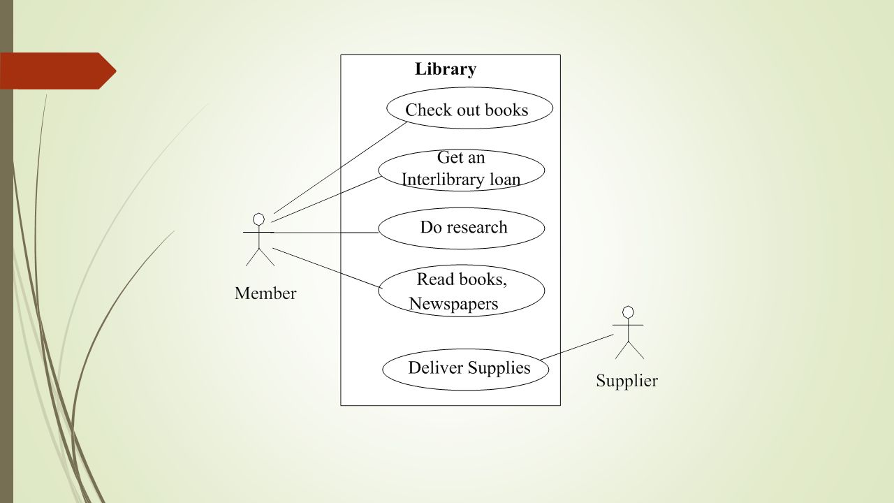
Elements of Use Case Models Use Case Actor Relationship Use Case Diagram Scenario System Boundary 8

9
4 use case symbols Actor and its name System boundary with system name Interaction Line and optional qualifier Use case and its name Budget Planning Not an information flow! Do something Line manager (secondary)
.")
10
Actors The term actor represents the role a user plays with respect to the system each actor represents a role that one or several users can play a user may play more than one role however, an actor should represent a single user You have to identify the actors and understand how they will use and interact with the system Slide 10

11
Actors: examples Customer : a person using the services of a system Member : a person using the services of a system (thus, a customer) after signing up (and in) Assistant : an employee who helps customers (e.g. by contacting members to inform them about new offers) 2013 - 2014 / I - 4-6 / Slide 11
 / I / Slide 11.")
12
Rules for Actors Actors to the outside of the System Boundary Actors should never communicate with each other Actors should be named with singular, business relevant nouns Actors should be roles not positions

14
The role of the Use Case Model The use case model tries to systematically identify uses of the system and therefore the systems responsibilities The use case model expresses what the application will do and not how The use case model can also be known as a what model Users are shown in the roles they play they are named Actors

15
What Use Case Modelling is NOT Does not model the system from the inside Are not effective in capturing the non-functional requirements Is not the same as functional decomposition Are not inherently object oriented Describe WHAT a system accomplished not how 15

16
Use-Case Modeling Developing Use-Case Diagrams Use cases are always initiated by an actor Use cases represent complete functionality of the system Relationships Between Use Cases Use cases may participate in relationships with other use-cases Two types Extends Adds new behaviors or actions to a use case Include One use case references another use case 16 20.16

17
Example A client makes a call that is taken by an operator, who determines the nature of the problem. Some calls can be answered immediately; other calls require research and a return call.

Similar presentations


: Object-Oriented Databases>")

