Download presentation
Presentation is loading. Please wait.

1
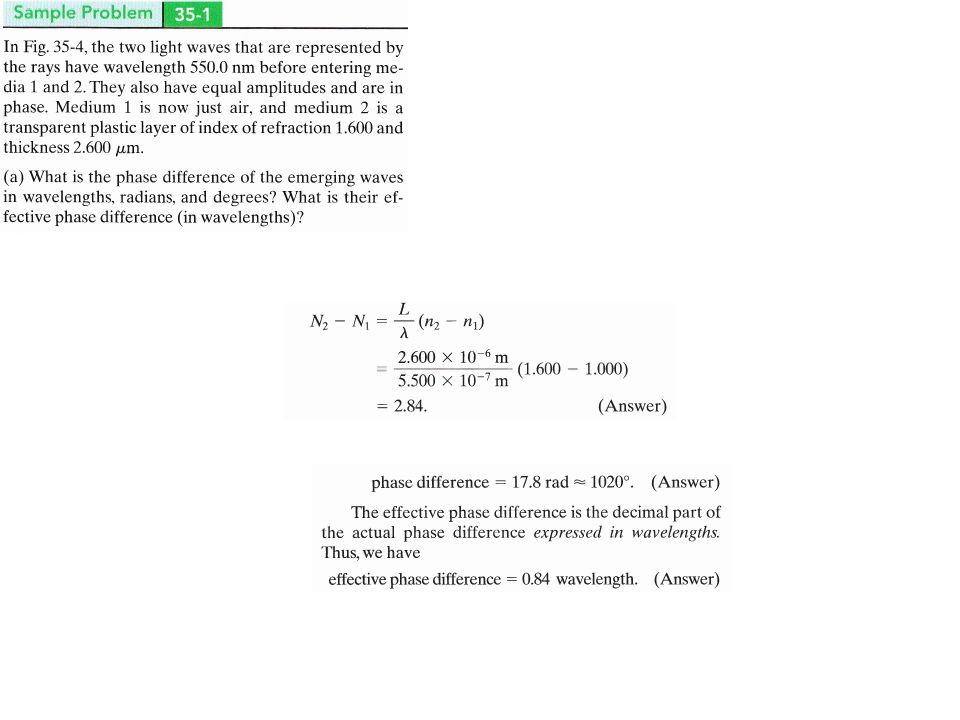
Optics (Lecture 2) Book Chapter 34,35
 Book Chapter 34,35")
2
images An image is a reproduction of an object via light.
If the image can form on a surface, it is a real image. Examples of real images include the image seen on a cinema screen. Real images can be produced by concave mirrors and converging lenses. It can exist even if no observer is present. If the image requires the visual system of an observer, it is a virtual image. A simple example is a flat mirror A real image occurs where rays converge, whereas a virtual image occurs where rays only appear to converge.

3
an object placed in front of a flat mirror.
Flat Mirror an object placed in front of a flat mirror.

5
Ray diagram of Mirror

6
Sign convention

7
Concave Mirror When the object is located so that the center of curvature lies between the object and a concave mirror surface, the image is real, inverted, and reduced in size.

8
Concave Mirror When the object is located between the focal point and a concave mirror surface, the image is virtual, upright, and enlarged.

9
When the object is in front of a convex mirror, the image is
virtual, upright, and reduced in size

10
Spherical Mirror Equation
The equation for image formation by rays near the optic axis (paraxial rays) of a mirror has the same form as the thin lens equation: From the geometry of the spherical mirror, note that the focal length is half the radius of curvature:
 of a mirror has the same form as the thin lens equation: From the geometry of the spherical mirror, note that the focal length is half the radius of curvature:")
11
As in the case of lenses, the cartesian sign convention is used here, and that is the origin of the negative sign above. The radius r for a concave mirror is a negative quantity (going left from the surface), and this gives a positive focal length, implying convergence.
, and this gives a positive focal length, implying convergence..")
12
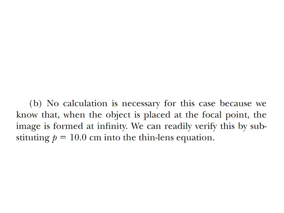
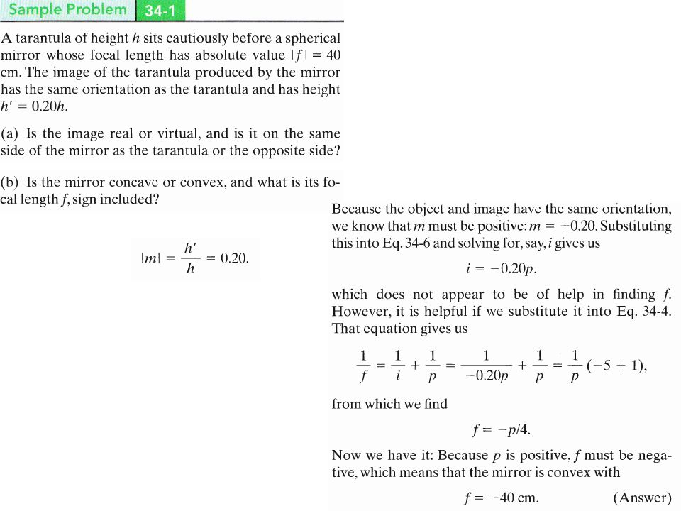
Exercise The object is positioned at the focal point of a mirror are reflected so that the image is formed at an infinite distance from the mirror; The M <1; the image is smaller than the object, and the –ve sign for M tells us that the image is inverted. Because q is positive, the image is located on the front side of the mirror and is real.

13
The image is twice as large as the object, and the positive sign for M indicates that the image is upright

14
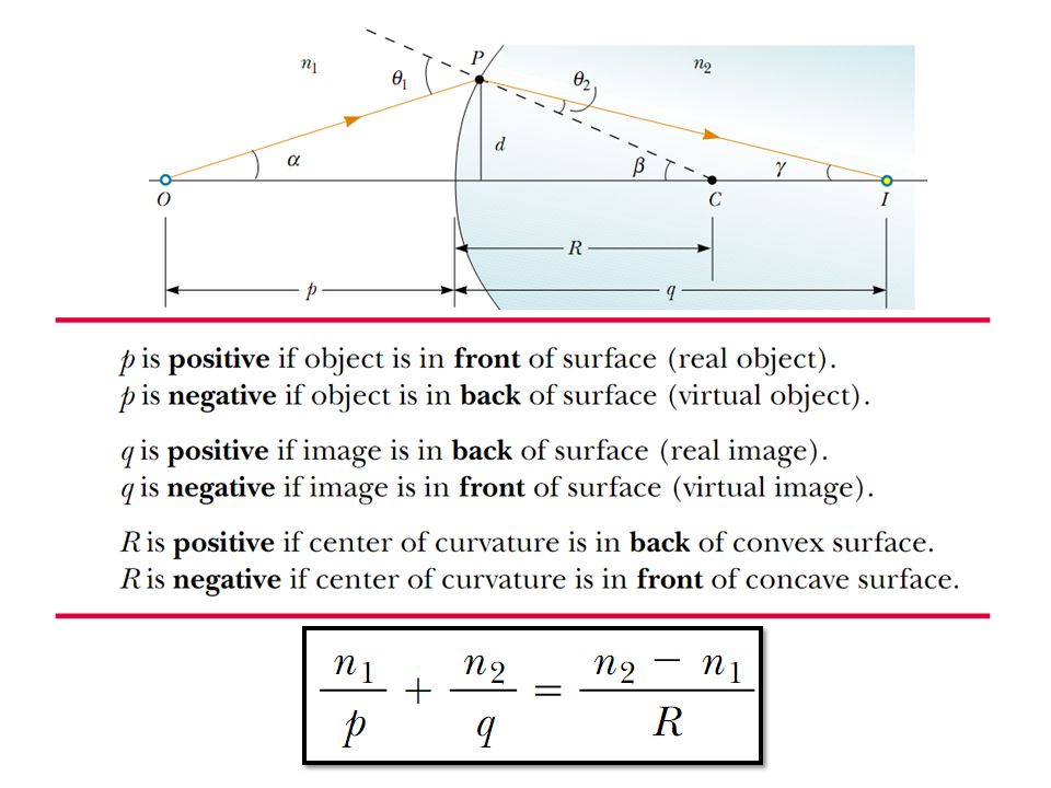
Six possible ways in which an image can be formed by refraction through a spherical surface of radius r and center of curvature C. The surface separates a medium with index of refraction n1 from a medium with index of refraction n2. The point object O is always in the medium with n1 to the left of the surface. The material with the lesser index of refraction is unshaded Real images are formed in (a) and (b); virtual images are formed in the other four situations. Solve Example 34.2
 and (b); virtual images are formed in the other four situations. Solve Example")
16
Ray diagram of Lens The image formed by a single lens can be located and sized with three principal rays. Examples are given for converging and diverging lenses and for the cases where the object is inside and outside the principal focal length. The "three principal rays" which are used for visualizing the image location and size are: A ray from the top of the object proceeding parallel to the centerline perpendicular to the lens. Beyond the lens, it will pass through the principal focal point. For a negative lens, it will proceed from the lens as if it emanated from the focal point on the near side of the lens.

17
A ray through the center of the lens, which will be un-deflected.
A ray through the principal focal point on the near side of the lens. It will proceed parallel to the centerline upon exit from the lens. The third ray is not really needed, since the first two locate the image.

18
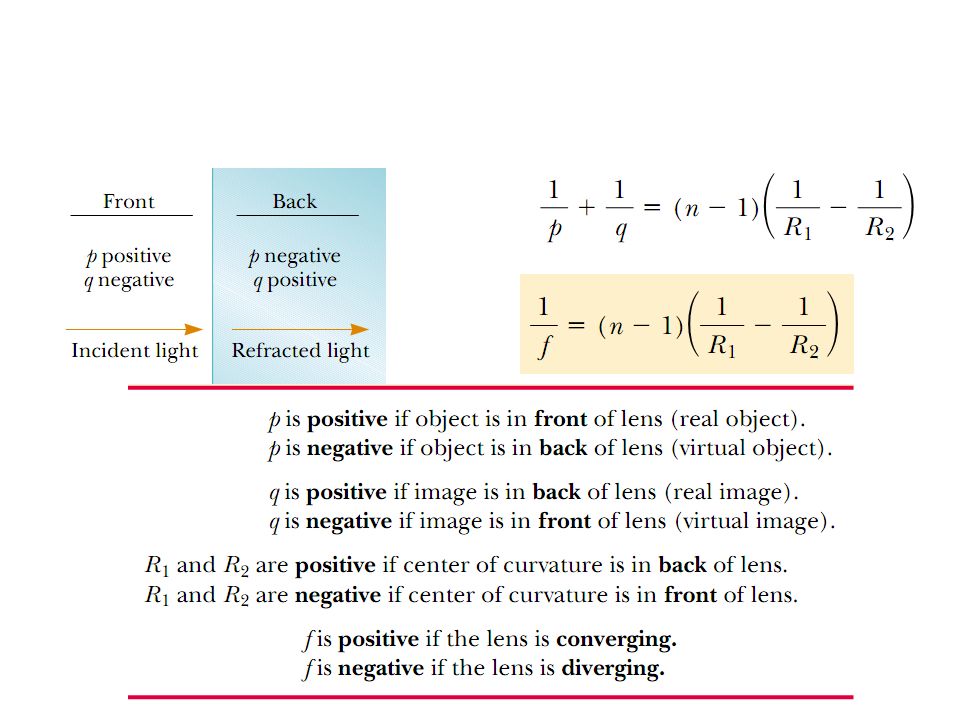
Thin Lens A lens is a transparent object with two refracting surfaces whose central axes coincide. The common central axis is the central axis of the lens. When a lens is surrounded by air, light refracts from the air into the lens, crosses through the lens, and then refracts back into the air. Each refraction can change the directionof travel of the light.

20
Example The negative sign tells us that the image is in front of the lens and virtual,

21
Example The positive sign indicates that the image is in back of the lens and real. the image is inverted.

23
The image is enlarged, and the
positive sign for M tells us that the image is upright,

24
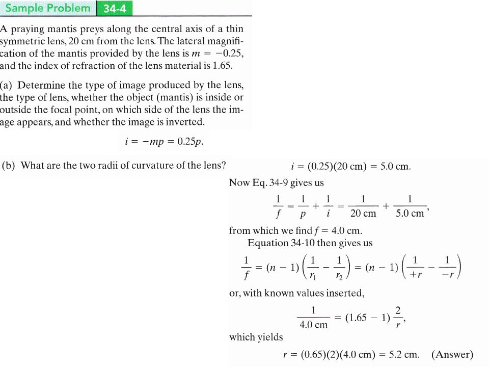
Example

26
Thin Lens

28
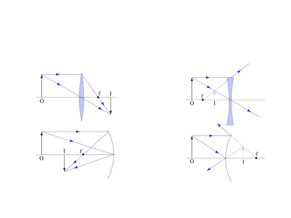
(a) A real, inverted image I is formed by a converging lens when the object O is outside the focal point (b) The image I is virtual and has the same orientation as O when O is inside the focal point. (c) A diverging lens forms a virtual image I, with the same orientation as the object O, whether O is inside or outside the focal point of the lens.
 A diverging lens forms a virtual image I, with the same orientation as the object O, whether O is inside or outside the focal point of the lens.")
29
Ray Diagrams for Convex Lenses
For an object outside the focal point, a real inverted image will be formed. For an object inside the focal point, a virtual erect image will be formed.

30
Real Image Formation If a luminous object is placed at a distance greater than the focal length away from a convex lens, then it will form an inverted real image on the opposite side of the lens. The image position may be found from the lens equation or by using a ray diagram.

31
Virtual Image Formation
Diverging lenses form reduced, erect, virtual images. Using the common form of the lens equation, f, P and i are negative quantities.

32
Ray Diagrams for Concave Lenses
The ray diagrams for concave lenses inside and outside the focal point give similar results: an erect virtual image smaller than the object. The image is always formed inside the focal length of the lens.

33
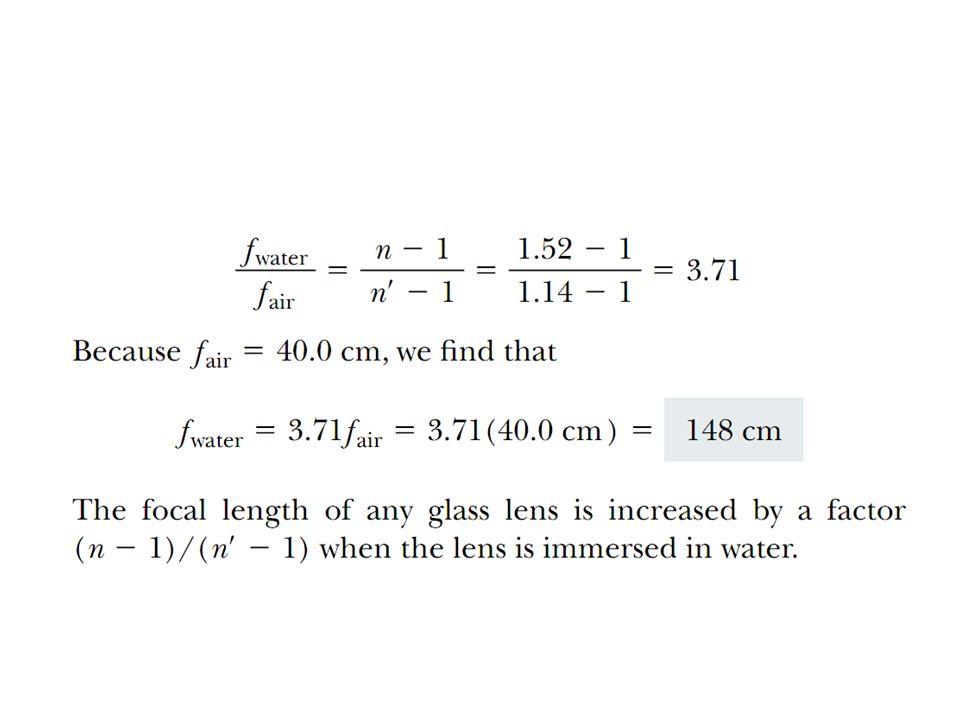
Focal Length and Lens Strength
The most important characteristic of a lens is its principal focal length, or its inverse which is called the lens strength or lens "power". Optometrists usually prescribe corrective lenses in terms of the lens power in diopters. The lens power is the inverse of the focal length in meters: the physical unit for lens power is 1/meter which is called diopter.

35
Lens-Maker's Formula For a thin lens, the power is approximately the sum of the surface powers. The radii of curvature here are measured according to the Cartesian sign convention. For a double convex lens the radius R1 is positive since it is measured from the front surface and extends right to the center of curvature. The radius R2 is negative since it extends left from the second surface

36
lmage Formation Spherical mirrors, spherical refracting surfaces, and thin lenses can form images of a source of light the object-by redirecting rays emerging from the source. The image occurs where the redirected rays cross (forming a real image) or where backward extensions of those rays cross (forming a virtual image). If the rays are sufficiently close to the central axis through the spherical mirror, refracting surface, or thin lens, we have the following relations between the object distance o or p (which is positive) and the image distance i (which is positive for real images and negative for virtual images)
 or where backward extensions of those rays cross (forming a virtual image). If the rays are sufficiently close to the central axis through the spherical mirror, refracting surface, or thin lens, we have the following relations between the object distance o or p (which is positive) and the image distance i (which is positive for real images and negative for virtual images)")
38
Convex Mirror Image A convex mirror forms a virtual image.

39
Using a ray parallel to the principal axis and one incident upon the center of the mirror, the position of the image can be constructed by back-projecting the rays which reflect from the mirror. The virtual image that is formed will appear smaller and closer to the mirror than the object.

40
Concave Mirror Image If the object is outside the focal length, a concave mirror will form a real, inverted image.

41
Concave Mirror Image If an object is placed inside the focal length of a concave mirror, and enlarged virtual and erect image will be formed behind the mirror

43
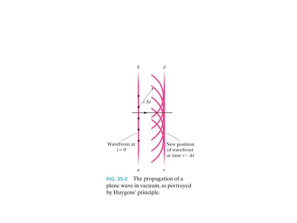
Huygen’s Principle

49
Diffraction When waves encounter an edge, an obstacle, or an aperture the size of which is comparable to the wavelength of the waves, those waves spread out as they travel and, as a result, undergo interference. This is called diffraction Diffraction is the constructive and destructive interference of two beams of light that results in a wave-like pattern.

50
Diffraction If a wave encounters a barrier that has an opening of dimensions similar to the wavelength, the part of the wave that passes through the opening will flare (spread) out-will diffract-into the region beyond the barrier.
 out-will diffract-into the region beyond the barrier.")
62
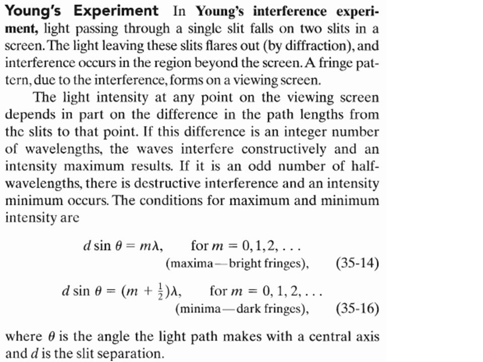
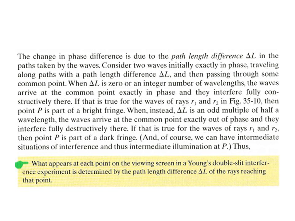
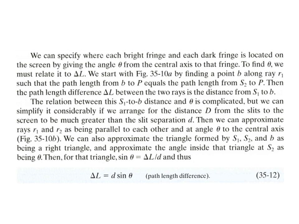
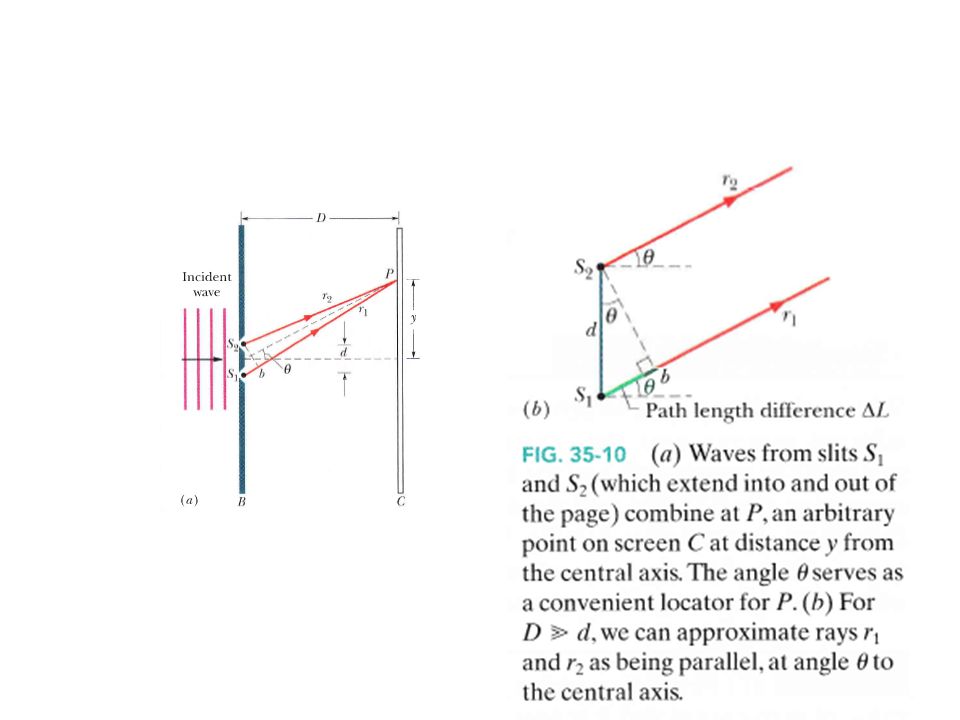
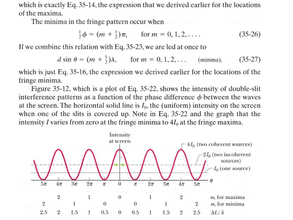
Locating the Fringes

68
Coherence Two sources of light are said to be coherent if the waves emitted from them have the same frequency and are 'phase-linked'; that is, they have a zero or constant phase difference

74
Newton’s Ring Newton’s Ring is an interference pattern caused by the reflection of light between two surfaces - a spherical surface and an adjacent flat surface. passing through, and λ is the wavelength of the light passing through the glass. When viewed with monochromatic light it appears as a series of concentric, alternating bright and dark rings centered at the point of contact between the two surfaces.

75
The light rings are caused by constructive interference between the light rays reflected from both surfaces, while the dark rings are caused by destructive interference. Also, the outer rings are spaced more closely than the inner ones.

76
The radius of the Nth Newton's bright ring is given by
where N is the bright ring number, R is the radius of curvature of the lens the light is

77
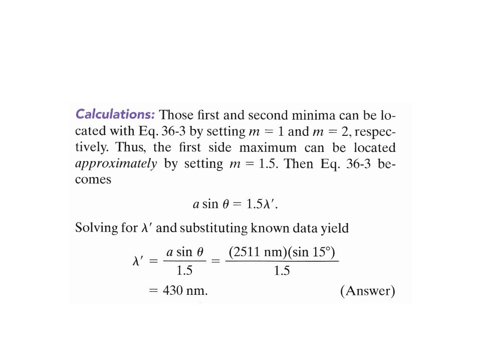
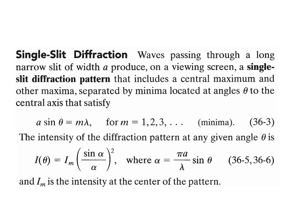
Fraunhofer diffraction
Fraunhofer diffraction is the special case where the incoming light (monochromatic) is assumed to be parallel and the image plane is assumed to be at a very large distance compared to the diffracting object. It occurs when planar waves are passed through an aperture or slit causing only the size of an observed aperture image to change due to the far-field location of observation and the increasingly planar nature of outgoing diffracted waves passing through the aperture.
 is assumed to be parallel and the image plane is assumed to be at a very large distance compared to the diffracting object. It occurs when planar waves are passed through an aperture or slit causing only the size of an observed aperture image to change due to the far-field location of observation and the increasingly planar nature of outgoing diffracted waves passing through the aperture.")
78
Fresnel diffraction Fresnel diffraction refers to the general case.
Fresnel diffraction or near-field diffraction is a process of diffraction that occurs when a wave passes through an aperture and diffracts in the near field, causing any diffraction pattern observed to differ in size and shape, depending on the distance between the aperture and the projection.

79
An example of an optical setup that displays Fresnel diffraction occurring in the near-field. On this diagram, a wave is diffracted and observed at point σ. As this point is moved further back, beyond the Fresnel threshold or in the far-field, Fraunhofer diffraction occurs.

80
Summary Fresnel diffraction occurs when:
Fraunhofer diffraction occurs when: a - aperture or slit size, λ - wavelength, L - distance from the aperture

Similar presentations