Download presentation
Presentation is loading. Please wait.

1
Microassembly – deterministic
Sequential: pick and place Keller Yeh Wafer scale On-wafer (Magnetic, triboelectric, motorized, residual stress, …) Wafer-to-wafer (Howe, Cohn, Bright) Micro-packaging
 Wafer-to-wafer (Howe, Cohn, Bright) Micro-packaging.")
2
Manual assembly (tweezers) Corner-Cube Retroreflectors Based on Structure-Assisted Assembly for Free-Space Optical Communication, Zhou, Kahn, Pister
 Corner-Cube Retroreflectors Based on Structure-Assisted Assembly for Free-Space Optical Communication, Zhou, Kahn, Pister")
4
Micro-Tweezers (memspi.com)
")
5
Tweezers holding optical fiber
Design: Chris Keller Fab: Sandia Courtesy: MEMS Precision Instruments

6
Tweezer gripping Hexsil gear
Courtesy: MEMS Precision Instruments

7
Comparison with Commercial subretinal tweezer (Storz)
Photos courtesy Chris Keller, MEMS Precision Instruments

8
Synthetic Insects (Smart Dust with Legs)
Goal: Make silicon walk. Autonomous Articulated Size ~ 1-10 mm Speed ~ 1mm/s

9
Actuating the Legs 1st Link Motor 2nd Link 1mm

10
Magnetic Parallel Assembly
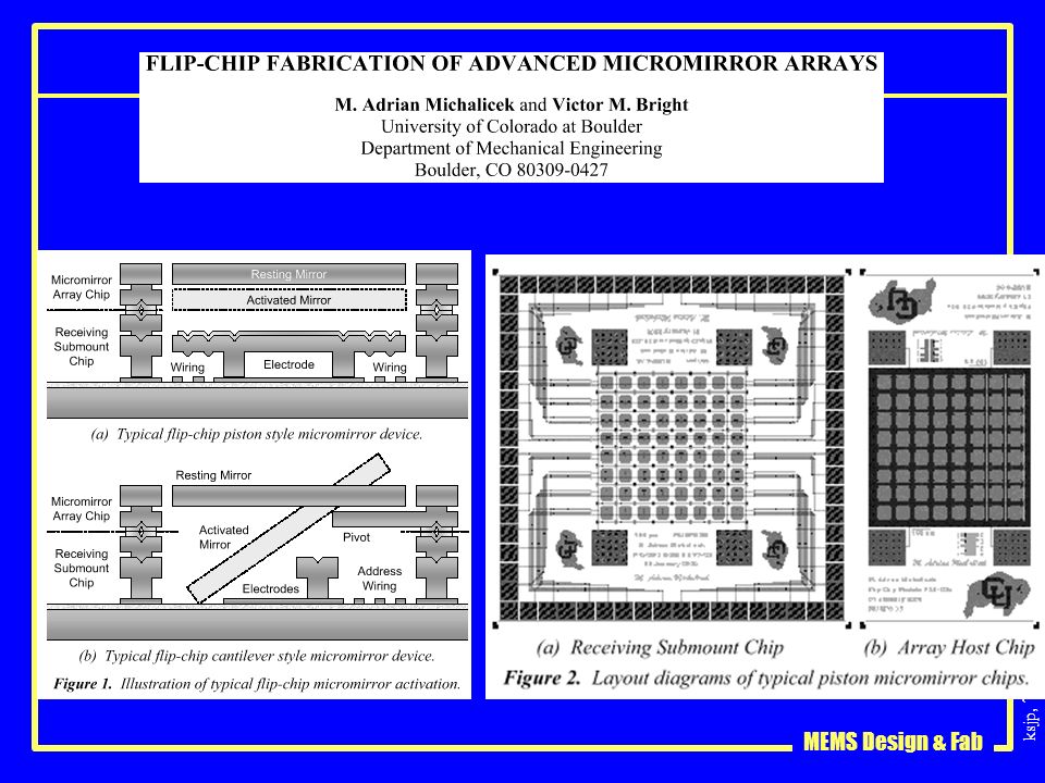
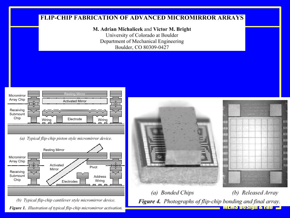
Parallel assembly of Hinged Microstructures Using Magnetic Actuation Yong Yi and Chang Liu Microelectronics Laboratory University of Illinois at Urbana-Champaign Urbana, IL 61801 Figure 1. (a) An SEM micrograph of a Type I structure. The flap is allowed to rotate about the Y- axis. (b) Schematic cross-sectional view of the structure at rest; (c) schematic cross-sectional view of the flap as Hext is increased. Figure 2. (a) SEM micrograph of a Type II structure. (b) Schematic cross-sectional view of the structure at rest; (c) schematic cross-sectional view of the structure when Hext is increased. Solid-State Sensor and Actuator Workshop Hilton Head 1998
 An SEM micrograph of a Type I structure. The flap is allowed to rotate about the Y- axis. (b) Schematic cross-sectional view of the structure at rest; (c) schematic cross-sectional view of the flap as Hext is increased. Figure 2. (a) SEM micrograph of a Type II structure. (b) Schematic cross-sectional view of the structure at rest; (c) schematic cross-sectional view of the structure when Hext is increased. Solid-State Sensor and Actuator Workshop. Hilton Head")
11
Sequential parallel assembly
Parallel assembly of Hinged Microstructures Using Magnetic Actuation Yong Yi and Chang Liu Microelectronics Laboratory University of Illinois at Urbana-Champaign Urbana, IL 61801 Figure 8. Schematic of the assembly process for the flap 3-D devices. (a) Both flaps in the resting position; (b) primary flap raised to 90º at Hext = H1; (c) full 3-D assembly is achieved at Hext = H2 (H2 > H1 ). Figure 9. An SEM micrograph of a 3-D device using three Type I flaps. The sequence of actuation is not critical to the assembly of this device. Solid-State Sensor and Actuator Workshop Hilton Head 1998
 Both flaps in the resting position; (b) primary flap raised to 90º at Hext = H1; (c) full 3-D assembly is achieved at Hext = H2 (H2 > H1 ). Figure 9. An SEM micrograph of a 3-D device using three Type I flaps. The sequence of actuation is not critical to the assembly of this device. Solid-State Sensor and Actuator Workshop. Hilton Head")
12
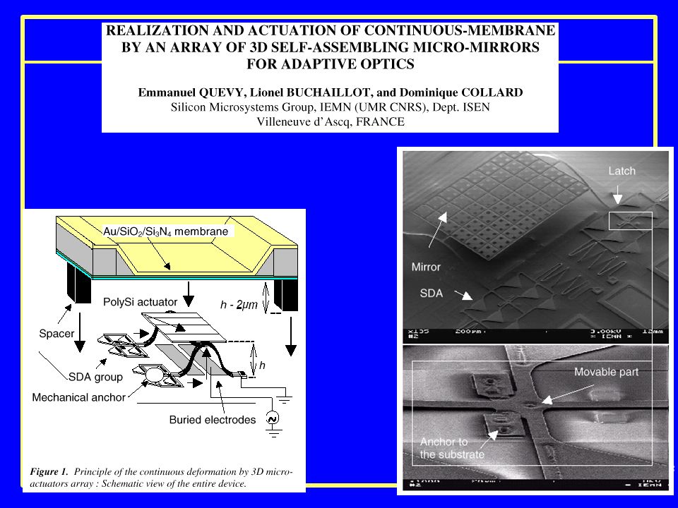
Assembly via Residual Stress
Low Insertion Loss Packaged and Fiber-Connectorized Si Surface-Micromachined Reflective Optical Switch V. Aksyuk, B. Barber, C. R. Giles, R. Ruel, L. Stulz, and D. Bishop Bell Laboratories, Lucent Technologies, 700 Mountain Ave. Murray Hill, NJ 07974 0.8 dB loss in transmission w/ AR coated fibers 2 dB reflection loss 0-80dB attenuation fibers mounted with UV cured adhesive 1550nm Later included in a closed loop feedback system actuator lands on dimples onto grounded pads. HH p 79- Figure 2. Self-Assembling optical shutter. High tensile residual stress metal is deposited on a polysilicon beam anchored at one end. Upon release the metal-poly sandwich structure deforms, moving the free end of the beam upward. The lifting structure engages the cut in the hinged-plate shutter causing it to rotate 90 degrees into tits operating position.

13
Parallel Assembly via Triboelectricity

14
OMM 16x16 switch From 256 hinged mirrors!

15
Parallel Assembly via Surface Tension
Reflow Silicon substrate Silicon substrate Compact, parallel process assembly Accuracy and reliability ? Syms, then Bright

16
Solder-assembly (Rich Syms)
")
17
Taxonomy of Microassembly
Parallel microassembly Multiple parts assembled simultaneously Deterministic: pre-determined destination for parts Stochastic: random process determines part destinations Serial microassembly “Pick and place” on a microscale Courtesy: Roger Howe, UCB

18
Parallel Microassembly Processes
K. Böhringer, et al, ICRA, Leuven, Belgium, May 1998 Courtesy: Roger Howe, UCB

19
Stochastic Parallel Microassembly
Agitated parts find minimum energy state via an annealing process Gravitational well: J. S. Smith, UC Berkeley and Alien Technology Corp., Morgan Hill, Calif. (video) Patterned chemical “binding sites” G. M. Whitesides, Harvard: hydrophobic surfaces formed by self-assembled monolayers define the binding site Courtesy: Roger Howe, UCB
 Patterned chemical binding sites G. M. Whitesides, Harvard: hydrophobic surfaces formed by self-assembled monolayers define the binding site. Courtesy: Roger Howe, UCB.")
20
Courtesy: Roger Howe, UCB
Biomimetic Approach Pattern part surfaces with hydrophobic and hydrophilic regions using self-assembled monolayers (SAMs). free energy cost of SAM-water interface is high hydrophobic regions act as binding sites Terfort, A. et al. Nature, 386, (1997). Courtesy: Roger Howe, UCB
. free energy cost of SAM-water interface is high. hydrophobic regions act as binding sites. Terfort, A. et al. Nature, 386, (1997). Courtesy: Roger Howe, UCB.")
21
Application to Microassembly
Pattern complementary hydrophobic shapes onto parts and substrates using SAMs. no shape constraints on parts no bulk micromachining of substrate submicron, orientational alignment Uthara Srinivasan, Ph.D. thesis, UC Berkeley Chem.Eng., May 2001 Courtesy: Roger Howe, UCB

22
Mirrors onto Microactuators
Self-assemble mirrors onto microactuator arrays Si (100) mirrors Nickel-polySi bimorph actuators We have used this self-assembly technique to place ultraflat single-crystal silicon micromirrors onto surface-micromachined microactuator arrays. The polySi actuator platform is actuated using nickel-poly-Si bimorphs. The binding site on the platform is a hexagonal shape of evaporated gold. A matching binding site also exists on the underside of the silicon mirror to be assembled. I’ll discuss how these binding sites are made hydrophobic in a few slides. This assembly demonstrates the process decoupling that can be achieved with microassembly. U. Srinivasan, M. Helmbrecht, C. Rembe, R. T. Howe, and R. S. Muller, IEEE Opto-MEMS 2000 Workshop, Kawai, Hawaii, Aug , 2000 Courtesy: Roger Howe, UCB
 mirrors. Nickel-polySi bimorph actuators. We have used this self-assembly technique to place ultraflat single-crystal silicon micromirrors onto surface-micromachined microactuator arrays. The polySi actuator platform is actuated using nickel-poly-Si bimorphs. The binding site on the platform is a hexagonal shape of evaporated gold. A matching binding site also exists on the underside of the silicon mirror to be assembled. I’ll discuss how these binding sites are made hydrophobic in a few slides. This assembly demonstrates the process decoupling that can be achieved with microassembly. U. Srinivasan, M. Helmbrecht, C. Rembe, R. T. Howe, and R. S. Muller, IEEE Opto-MEMS 2000 Workshop, Kawai, Hawaii, Aug , Courtesy: Roger Howe, UCB.")
23
Courtesy: Roger Howe, UCB
Unreleased Mirrors oxide Si mirror binding site Si(100) mirror array with binding sites, fabricated from SOI wafer And here we have the silicon (100) mirrors with gold binding sites which have been fabricated from a silicon-on-insulator wafer of silicon thickness of 15 um. The exposed sacrificial oxide is visible between the mirrors. The oxide is etched using HF, and the mirrors are released into solution. Courtesy: Roger Howe, UCB
 mirror array with binding sites, fabricated from SOI wafer. And here we have the silicon (100) mirrors with gold binding sites which have been fabricated from a silicon-on-insulator wafer of silicon thickness of 15 um. The exposed sacrificial oxide is visible between the mirrors. The oxide is etched using HF, and the mirrors are released into solution. Courtesy: Roger Howe, UCB.")
24
Courtesy: Roger Howe, UCB
Mirrors in Solution This photo shows the released mirrors floating in water. Next, the binding sites are treated to render tham hydrophobic. Courtesy: Roger Howe, UCB

25
Mirror on Released Actuator
assembled mirror binding site Here is a SEM of an assembled ultraflat mirror on a released microactuator. Binding sites without mirrors are also shown. Courtesy: Roger Howe, UCB

26
Mirrors on Microactuators
assembled mirror Here we have 7 silicon mirrors self-assembled onto a microactuator array under water. After this picture was taken, the adhesive was heat-cured and the microactuators were released using HF and dried with carbon dioxide critical point drying. The adhesive withstood this release process. Courtesy: Roger Howe, UCB

27
Courtesy: Roger Howe, UCB
Mirror Curvature Heat-cured acrylate adhesive Mirror curvature less than 30 nm Using stroboscopic interferometry, we measured the mirror curvature as less than 30 nm with the heat cured acrylate adhesive. This is well within lambda/10 for red light. Courtesy: Roger Howe, UCB

28
Research Challenges for Self-Assembly Processes
Assembly extensions: multi-pass and multi-part simultaneous assembly Reduce area consumed by binding site, in order to achieve: “High quality” mechanical interconnects “High density” electrical interconnects Courtesy: Roger Howe, UCB

29
Post-Assembly Processes
Polymer adhesives are not sufficient for many MEMS applications Good interfaces require high temperatures (> 450o C), which can damage micro-components Potential solutions: Local heating through laser Local resistive heating (Prof. Liwei Lin, UC Berkeley) Courtesy: Roger Howe, UCB
, which can damage micro-components. Potential solutions: Local heating through laser. Local resistive heating (Prof. Liwei Lin, UC Berkeley) Courtesy: Roger Howe, UCB.")
30
Chip-to-chip and wafer-wafer assembly
Flat, thin gold mirror with a thick Copper frame transferred from source Substrate to MUMPS die. Maharbiz, Howe, Pister, Transducers 99 MUMPS part by M. Helmbrecht

31
Moore’s Law, take 2 Nanochips on a dime (Prof. Steve Smith, EECS)
")
35
Remove substrate!

36
Could be 2-axis

38
Packaging IC Packaging extremely well developed Not well addressed
Reliability Thermal conductivity Cost Size Not well addressed Packaging with unfilled volumes Packaging in non-standard ambients Vacuum Dry N2 Moist N2 100 mTorr +/- 1% Fiber feedthroughs Somewhat addressed Optical I/O Packaging induced stresses

39
2x2 MEMS Fiber Optic Switches
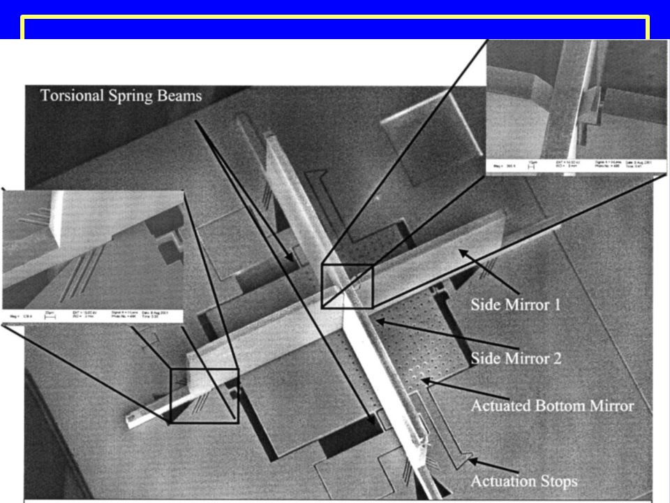
2x2 MEMS Fiber Optic Switches with Silicon Sub-Mount for Low-Cost Packaging Shi-Sheng Lee, Long-Sun Huang, Chang-Jin “CJ” Kim and Ming C. Wu Electrical Engineering Department, UCLA 63-128, engineering IV Building, Los Angeles, California Mechanical and Aerospace Engineering Department 85 V actuation. Smoothly controllable to 21degrees, then snaps to 45. Releases at 53V. Switches in less than 1 ms. Insertion loss is 10 dB! HH pp Substrate is 2 wafers machined on 3 sides. Figure 3. SEM of the torsion mirror device. Figure 1. SEM of the 2x2 MEMS fiber optic switch.

40
2x2 MEMS Fiber Optic Switches
Introduction to MEMS 2x2 MEMS Fiber Optic Switches 2x2 MEMS Fiber Optic Switches with Silicon Sub-Mount for Low-Cost Packaging Shi-Sheng Lee, Long-Sun Huang, Chang-Jin “CJ” Kim and Ming C. Wu Electrical Engineering Department, UCLA 63-128, engineering IV Building, Los Angeles, California Mechanical and Aerospace Engineering Department Figure 4. SEM of the vertical torsion mirror. Figure 10. SEM of the fiber and ball lens assembly. Solid-State Sensor and Actuator Workshop Hilton Head 1998

43
Assembly - Summary Pick-and-place assembly is the standard of the IC industry! Chips, passives into lead frames Bond wires Cost is ~1 penny/operation Parallel assembly is coming Wafer-wafer transfer (deterministic) Fluidic self-assembly (stochastic)
 Fluidic self-assembly (stochastic)")
Similar presentations
>")


 Wolfgang Borchardt February 13, 2008.>")


 and provides imprint services. Stamps made in Siliocn, Quartz, and Nickel.>")


