Download presentation
Presentation is loading. Please wait.

1
Groundwater Continued

2
Aquifers Consolidated Unconsolidated Confined Unconfined

3
Unconsolidated Aquifer
Basic Aquifer Classification Consolidated Aquifer Unconsolidated Aquifer Unconsolidated or Consolidated Unconsolidated: granular sand or gravel Consolidated: sandstone, limestone, granite Can be low-yield or high-yield Aquifers occur in either consolidated or unconsolidated ground formations. Consolidated aquifers hold water in the cracks of solid rock, and the amount of water available depends upon the size and number of cracks. Unconsolidated aquifers hold water in a mixture of sand and gravel. The Snake River aquifer in southern Idaho is an example of a consolidated aquifer, and the Rathdrum aquifer in northern Idaho is an example of an unconsolidated aquifer. Granite, sandstone Limestone, sand/gravel

4
Geologic or Soil material
Unconfined Aquifer Water High permeability Low Conductivity Geologic or Soil material Conductivity: the ease with which water moves through material

5
Confined Aquifer An inclined, water-bearing formation
located below an impermeable layer of clay, rock, or shale. Flow High pressure

6
Confined and Unconfined
Flow aquitard High pressure

7
Florida’s Aquifers

8
Florida’s Aquifers Florida has both confined and unconfined aquifers
Florida exists on a raised platform The Florida platform was dominated by carbonate deposition from the Jurassic (-200 my) to the Miocene (-25 my). 4. During the Miocene, clayey sediments blanketed the platform. 5. These sediments form a confining unit for Florida’s main aquifer 6. The major aquifer is a consolidated, carbonate confined aquifer. 7. Unconfined aquifers exist above the clay confining unit. sediments Suwannee Current Georgia Channel
 to the Miocene (-25 my). 4. During the Miocene, clayey sediments blanketed the platform. 5. These sediments form a confining unit for Florida’s main aquifer. 6. The major aquifer is a consolidated, carbonate confined aquifer. 7. Unconfined aquifers exist above the clay confining unit. sediments. Suwannee Current. Georgia Channel.")
9
Basics Recent Deposits Miocene Jurassic To Miocene Sands Clay
25 to 5 Mya Jurassic To Miocene CaCO3 200 Mya to 25 Mya

10
Sinkholes and springs are a product of the geology of Florida
Solution cavities exist in the limestone Water in cavities is under pressure Sinkholes: collapse of material into cavities Springs: water bursts through thin confining units

11
Springs Springs form best when the overlying clay layer is thin.

12
Springs First magnitude: 100 ft3/s Florida: 27 of 78 nationally
Hawthorne Thickness First magnitude: 100 ft3/s Florida: 27 of 78 nationally (64.6 million gallons per day) Thin or absent 30 – 200 ft sandy 30 – 200 ft clayey Confining unit less than 100 feet thick or is absent > 200 ft thick Springs are places where ground water discharges through natural openings in the ground. Springs may vary greatly in the volume of water they discharge; some springs are small enough to be expressed only as seeps where water oozes slowly from the aquifer, whereas others are large enough to form the headwaters of large rivers. The water discharged by a spring may be from an aquifer that is unconfined (water-table conditions) or confined (artesian conditions). Springs issuing from an unconfined aquifer tend to have a small, extremely variable flow and are directly and quickly affected by variations in precipitation. These springs may cease flowing during periods of less than normal precipitation. In contrast, springs issuing from a confined aquifer have a more constant flow because their flow is supplied by a much greater replenishment area. Accordingly, such springs tend to be unaffected by variations in precipitation unless there is prolonged drought. Springs are common in areas of karst topography. Spring flow is controlled by the size of the replenishment area, the difference in altitude between the spring opening or openings and the water level in the aquifer, and the size of the opening or openings through which the springs issue. Factors that have lesser effects on spring flow include atmospheric-pressure changes, earth and oceanic tides, and pumping of wells located near springs. Florida has 27 first-magnitude springs (springs with a flow of 100 cubic feet per second or more) out of a total of 78 in the entire Nation. The location of these springs is shown in figure 57. All of them issue from the Upper Floridan aquifer, and practically all of them are located in areas where the upper confining unit of the Floridan aquifer system either is less than 100 feet thick or is absent. The distribution of large springs discharging from the Floridan aquifer system, like the areas of greatest transmissivity within the aquifer system, is the direct result of dissolution of carbonate rocks, which results in the development of large conduits. Many of these caverns channel the ground water to the point where they are exposed at land surface and become the orifices of major springs (fig. 58).
 Thin or absent. 30 – 200 ft sandy. 30 – 200 ft clayey. Confining unit less than. 100 feet thick or is absent. > 200 ft thick. Springs are places where ground water discharges through natural openings in the ground. Springs may vary greatly in the volume of water they discharge; some springs are small enough to be expressed only as seeps where water oozes slowly from the aquifer, whereas others are large enough to form the headwaters of large rivers. The water discharged by a spring may be from an aquifer that is unconfined (water-table conditions) or confined (artesian conditions). Springs issuing from an unconfined aquifer tend to have a small, extremely variable flow and are directly and quickly affected by variations in precipitation. These springs may cease flowing during periods of less than normal precipitation. In contrast, springs issuing from a confined aquifer have a more constant flow because their flow is supplied by a much greater replenishment area. Accordingly, such springs tend to be unaffected by variations in precipitation unless there is prolonged drought. Springs are common in areas of karst topography. Spring flow is controlled by the size of the replenishment area, the difference in altitude between the spring opening or openings and the water level in the aquifer, and the size of the opening or openings through which the springs issue. Factors that have lesser effects on spring flow include atmospheric-pressure changes, earth and oceanic tides, and pumping of wells located near springs. Florida has 27 first-magnitude springs (springs with a flow of 100 cubic feet per second or more) out of a total of 78 in the entire Nation. The location of these springs is shown in figure 57. All of them issue from the Upper Floridan aquifer, and practically all of them are located in areas where the upper confining unit of the Floridan aquifer system either is less than 100 feet thick or is absent. The distribution of large springs discharging from the Floridan aquifer system, like the areas of greatest transmissivity within the aquifer system, is the direct result of dissolution of carbonate rocks, which results in the development of large conduits. Many of these caverns channel the ground water to the point where they are exposed at land surface and become the orifices of major springs (fig. 58).")
13
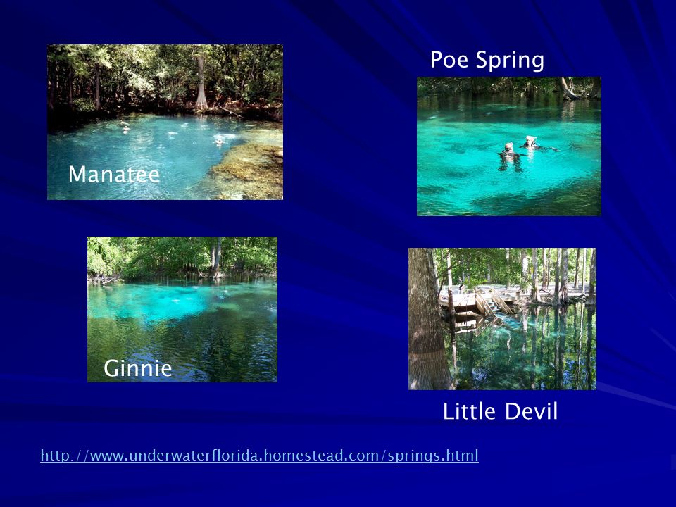
Poe Spring Manatee Ginnie Little Devil
14
Florida’s Dominant Aquifer Systems
Florida is the largest groundwater user east of the Mississippi

15
Floridan Aquifer Biscayne Aquifer Intermediate aquifer Unconfined

16
Sea Levels Temporary reestablishment of carbonate deposition

17
The Floridan Aquifer

18
The Floridan Aquifer Confined 100,000 square miles southern Alabama
southeastern Georgia southern South Carolina all of Florida Miocene clay deposits (Hawthorne) are the confining unit
 are the confining unit.")
19
Withdrawals 3 billion gallons per day of freshwater withdrawn
Agriculture – 39% Domestic use – 47% Industry – 8.5% Misc.- 5.5% The Floridan aquifer system provides water for several large cities, including Savannah and Brunswick in Georgia; and Jacksonville, Tallahassee, Orlando, and St. Petersburg in Florida. In addition, the aquifer system provides water for hundreds of thousands of people in smaller communities and rural areas. Locally, the Floridan is intensively pumped for industrial and irrigation supplies. During 1985, an average of about 3 billion gallons per day of freshwater was withdrawn from the Floridan for all purposes.

20
Water-Bearing Units CaCO3 + MgCO3
A thick sequence of carbonate rocks (limestone and dolomite) CaCO3 + MgCO3 The thickest and most productive formations of the system are the Avon Park Formation and the Ocala Limestone of Eocene age (37-58 million years ago) A thick sequence of carbonate rocks (limestone and dolomite) of Tertiary age comprise the Floridan aquifer system. The thickest and most productive formations of the system are the Avon Park Formation and the Ocala Limestone of Eocene age (fig. 49). The Suwannee Limestone (Oligocene age) also is a principal source of water, but it is thinner and much less areally extensive than the Eocene formations. The Tampa Limestone of Miocene age is part of the Floridan in only a few places where it is sufficiently permeable to be an aquifer. Both the Suwannee and the Tampa Limestones are discontinuous. The lower part of the Avon Park Formation, the Oldsmar Formation of early Eocene age, and the upper part of the Cedar Keys Formation of Paleocene age also are included in the Floridan where they are highly permeable. Limestone beds in the lower part of the Hawthorn Formation of Miocene age are considered part of the Floridan by some, but are excluded from it in this Atlas because the permeability of these beds is thought to be minimal. The base of the aquifer system in much of Florida consists of nearly impermeable anhydrite beds in the Cedar Keys Formation. In northern peninsular Florida, the Paleocene and lowermost Eocene rocks contain sand and are much less permeable than the carbonate rocks of the Floridan. Due to the contrast in permeability, these sandy strata form the base of the Floridan aquifer system in this area. Locally, in south-central Georgia and northern peninsular Florida, evaporite minerals have filled the pore spaces in upper Eocene rocks, and these low-permeability beds comprise the base of the system.
 CaCO3 + MgCO3. The thickest and most productive formations of the system are the Avon Park Formation and the Ocala Limestone of Eocene age (37-58 million years ago) A thick sequence of carbonate rocks (limestone and dolomite) of Tertiary age comprise the Floridan aquifer system. The thickest and most productive formations of the system are the Avon Park Formation and the Ocala Limestone of Eocene age (fig. 49). The Suwannee Limestone (Oligocene age) also is a principal source of water, but it is thinner and much less areally extensive than the Eocene formations. The Tampa Limestone of Miocene age is part of the Floridan in only a few places where it is sufficiently permeable to be an aquifer. Both the Suwannee and the Tampa Limestones are discontinuous. The lower part of the Avon Park Formation, the Oldsmar Formation of early Eocene age, and the upper part of the Cedar Keys Formation of Paleocene age also are included in the Floridan where they are highly permeable. Limestone beds in the lower part of the Hawthorn Formation of Miocene age are considered part of the Floridan by some, but are excluded from it in this Atlas because the permeability of these beds is thought to be minimal. The base of the aquifer system in much of Florida consists of nearly impermeable anhydrite beds in the Cedar Keys Formation. In northern peninsular Florida, the Paleocene and lowermost Eocene rocks contain sand and are much less permeable than the carbonate rocks of the Floridan. Due to the contrast in permeability, these sandy strata form the base of the Floridan aquifer system in this area. Locally, in south-central Georgia and northern peninsular Florida, evaporite minerals have filled the pore spaces in upper Eocene rocks, and these low-permeability beds comprise the base of the system.")
21
600 1200 1800 2400 Thickness In feet 3000

22
Biscayne Aquifer surficial Floridan Aquifer Intermediate aquifer

23
The Intermediate Aquifer System
In southwestern Florida, aquifers that lie between the surficial aquifer system and the Floridan aquifer system are collectively referred to as the intermediate aquifer system. This aquifer system starts in Hillsborough and Polk counties and extends south through Collier County. In southwestern Florida, aquifers that lie between the surficial aquifer system and the Floridan aquifer system are collectively referred to as the intermediate aquifer system. This aquifer system starts in Hillsborough and Polk counties and extends south through Collier County. The intermediate aquifer system is under confined conditions and is mainly comprised of permeable layers of sand, shell and limestone separated by clay confining units. It is the main source of water supply for Sarasota, Charlotte and Lee counties where the underlying Floridan aquifer contains brackish water. Much of the water pumped from this aquifer system is used for agriculture. In most places, water percolates down from the surficial aquifer system above to the intermediate aquifer system. Lateral flow is generally from a high area in Polk County towards major surface water features and the Gulf of Mexico.

24
The Intermediate Aquifer System
Between the surficial aquifer system and the Floridan aquifer system Used where the underlying Floridan aquifer system is deeply buried and/or contains brackish or saltwater. Clay confining units are above the Floridan and below the surficial aquifer. Artesian, but yields less water than the Floridan In southwestern Florida, aquifers that lie between the surficial aquifer system and the Floridan aquifer system are collectively referred to as the intermediate aquifer system. This aquifer system starts in Hillsborough and Polk counties and extends south through Collier County. The intermediate aquifer system is under confined conditions and is mainly comprised of permeable layers of sand, shell and limestone separated by clay confining units. It is the main source of water supply for Sarasota, Charlotte and Lee counties where the underlying Floridan aquifer contains brackish water. Much of the water pumped from this aquifer system is used for agriculture. In most places, water percolates down from the surficial aquifer system above to the intermediate aquifer system. Lateral flow is generally from a high area in Polk County towards major surface water features and the Gulf of Mexico. Sand, limestone, shell beds 298 million gallons per day

25
Intermediate Aquifer confined Sand, shell, limestone
the water in the aquifer system is under confined conditions except locally, where the upper confining unit is absent and the system is in direct hydraulic contact with the overlying surficial aquifer system. In most places, water moves downward from the surficial aquifer system and through the upper confining unit of the intermediate aquifer system; most of this water then follows short flow paths and discharges to surface drainage. Some water, however, percolates downward through the lower confining unit of the system to recharge the underlying Floridan aquifer system. Locally, in western Charlotte and Lee Counties, some water leaks upward from the Floridan to the intermediate aquifer system.

26
The Intermediate Aquifer System
Polk Co. In southwestern Florida, aquifers that lie between the surficial aquifer system and the Floridan aquifer system are collectively referred to as the intermediate aquifer system. This aquifer system starts in Hillsborough and Polk counties and extends south through Collier County. Collier Co.

27
Polk: 120 ft flow Main source of
Because the intermediate aquifer system does not yield as much water as other aquifers, it is used only in places where water from surficial aquifers or the Floridan aquifer system is not adequate in amount or quality. In southwestern Florida, for example, the underlying Floridan aquifer system contains non-potable water, thus the intermediate aquifer system is the main source of water supply for Charlotte, Lee, and Sarasota counties. It is the main source of water supply for Sarasota, Charlotte and Lee counties where the underlying Floridan aquifer contains brackish water. Much of the water pumped from this aquifer system is used for agriculture. In most places, water percolates down from the surficial aquifer system above to the intermediate aquifer system. Lateral flow is generally from a high area in Polk County towards major surface water features and the Gulf of Mexico. Main source of water supply for Charlotte, Lee, and Sarasota counties. flow

28
Withdrawal = 3 billion gal/day
Comparison Floridan Aquifer: Intermediate Aquifer: Withdrawal = 3 billion gal/day Withdrawal = 298 million gal/day Intermediate aquifer is used where the Floridan is inadequate

29
Surficial aquifers: The Biscayne

30
Surficial aquifers Water stored above an impermeable
layer and unconfined at the surface

31
Surficial aquifers water Soils or Geologic Materials high conductivity
low conductivity

32
Biscayne Aquifer 4,000 square miles Dade Broward Palm Beach

33
Biscayne Aquifer Plio-pliestocence 786 million gallons/day
highly permeable sand, limestone, sandstone, shells, marl Plio-pliestocence 786 million gallons/day 70 % for public supply Miocene Eocene low-permeability sandy silt The base of the Biscayne aquifer in Dade County and southern Broward County is a low-permeability sandy silt that is part of the Pliocene Tamiami Formation. Marls are calcium carbonate or lime-rich muds or mudstones which contain variable amounts of clays and calcite or aragonite. The term is most often used to describe lacustrine (lake) sediments but may also be used for marine deposits. The term 'marl' is widely used in North American geology, while the term seekreide is used in European references. A deposit containing spheroidal grains with a mineral cortex, most commonly calcite or aragonite, accreted around a nucleus formed primarily of shell fragments or quartz grains. Marls: carbonate-rich muds containing clays and calcite Oolitic limestone: spheroidal carbonate grains with a mineral cortex
 sediments but may also be used for marine deposits. The term marl is widely used in North American geology, while the term seekreide is used in European references. A deposit containing spheroidal grains with a mineral cortex, most commonly calcite or aragonite, accreted around a nucleus formed primarily of shell fragments or quartz grains. Marls: carbonate-rich muds containing clays and calcite. Oolitic limestone: spheroidal carbonate grains with a mineral cortex.")
34
Thickness 240 ft The base is somewhat irregular but generally slopes seaward from the western limit of the aquifer, where it is at the land surface, to a depth of about 240 feet below sea level near Boca Raton. Throughout much of the mapped area, the top of the aquifer is at or near the land surface. Accordingly, thickness of the aquifer can be estimated by subtracting the altitude of the base of the aquifer from the altitude of the land surface at a given point. The aquifer is wedge-shaped and ranges in thickness from a few feet near its western limit to about 240 feet near the coast.

35
Water in the Biscayne

36
Recharge and Flow Recharge Flow

37
Pesticides, fertilizers, landfills, septic systems, injection wells
Because the Biscayne aquifer is highly permeable and is at or near the land surface practically everywhere, it is readily susceptible to ground-water contamination. Because of the high permeability of the aquifer, most contaminants are rapidly flushed. Major sources of contamination are saltwater encroachment and infiltration of contaminants carried in canal water. Additional sources include direct infiltration of contaminants, such as chemicals or pesticides applied to or spilled on the land, or fertilizer carried in surface runoff; landfills; septic tanks; sewage-plant treatment ponds; and wells used to dispose of storm runoff or industrial waste. Most disposal wells are completed in aquifers containing saltwater that underlie the Biscayne aquifer, but they are a potential source of contamination where they are improperly constructed. Numerous hazardous-waste sites have been identified in the area underlain by the Biscayne aquifer, and three unlined landfills are known to have contaminated the aquifer. Remedial action to prevent further contamination is underway at many of these sites Salt water

38
Salinization pumping

39
Coastal Canals

40
Inland Canals Flood Control pollutants
The hydraulic connection between the Biscayne aquifer and the canals that cross it is direct. Water passes freely from the canals into the aquifer and vice versa. A decline in the water level of a canal lowers the adjacent water table of the aquifer almost immediately. Similarly, a rise in the water level in a canal is rapidly followed by a rise in the water table of the aquifer adjacent to the canal. These canal-aquifer water-level relations are shown schematically in figure 36. The arrows show the direction that water moves when the water level of the canal is lower (fig. 36A) and higher (fig. 36B) than the water table in the aquifer. The degree of connection decreases as fine sediment settles out of the canal water and lines the canal bottom. Accordingly, the degree of connection may change from time to time because of either accumulation of these sediments or their removal during runoff from intense storms. The hydraulic connection between the canals and the aquifer results in both benefits and problems. Perhaps the most obvious benefit is the ability of the canals to rapidly remove excess surface and ground water, thereby preventing flooding in low-lying interior areas. A more subtle benefit is the ability to move water from inland parts of the aquifer to coastal areas through the canals, allowing ground-water levels near the coast to remain high enough to retard saltwater encroachment during periods of less than normal precipitation. Problems also can result from the direct hydraulic connection. For example, aquifer contamination by any pollutants in the canal water can be both rapid and widespread. pollutants
 and higher (fig. 36B) than the water table in the aquifer. The degree of connection decreases as fine sediment settles out of the canal water and lines the canal bottom. Accordingly, the degree of connection may change from time to time because of either accumulation of these sediments or their removal during runoff from intense storms. The hydraulic connection between the canals and the aquifer results in both benefits and problems. Perhaps the most obvious benefit is the ability of the canals to rapidly remove excess surface and ground water, thereby preventing flooding in low-lying interior areas. A more subtle benefit is the ability to move water from inland parts of the aquifer to coastal areas through the canals, allowing ground-water levels near the coast to remain high enough to retard saltwater encroachment during periods of less than normal precipitation. Problems also can result from the direct hydraulic connection. For example, aquifer contamination by any pollutants in the canal water can be both rapid and widespread. pollutants.")
41
Three Major Florida Aquifers
Floridan Aquifer: Intermediate Aquifer: Biscayne Aquifer Withdrawal = 3 billion gal/day Withdrawal = 298 million gal/day Withdrawal = 786 million gallons/day Total = billion gallons/day

42
Floridan Aquifer Biscayne Aquifer Intermediate aquifer Unconfined

Similar presentations


