Download presentation
Presentation is loading. Please wait.

1
Future Circular Collider
(FCC) Study M. Benedikt gratefully acknowledging input from FCC global design study team
 Study. M. Benedikt. gratefully acknowledging input from FCC global design study team.")
2
Outline Introduction, motivation, scope Parameters & design challenges
Study organization and status Summary

3
Summary: European Strategy Update 2013
Design studies and R&D at the energy frontier ….“to propose an ambitious post-LHC accelerator project at CERN by the time of the next Strategy update”: d) CERN should undertake design studies for accelerator projects in a global context, with emphasis on proton-proton and electron-positron high-energy frontier machines. These design studies should be coupled to a vigorous accelerator R&D programme, including high-field magnets and high-gradient accelerating structures, in collaboration with national institutes, laboratories and universities worldwide. strategy adopted at Brussels in May 2013, during exceptional session of the CERN Council in presence of the European Commission
 CERN should undertake design studies for accelerator projects in a global context, with emphasis on proton-proton and electron-positron high-energy frontier machines. These design studies should be coupled to a vigorous accelerator R&D programme, including high-field magnets and high-gradient accelerating structures, in collaboration with national institutes, laboratories and universities worldwide. strategy adopted at Brussels in May 2013, during exceptional session of the CERN Council in presence of the European Commission.")
4
Future Circular Collider Study - SCOPE
CDR and cost review for the next ESU (2018) Forming an international collaboration to study: pp-collider (FCC-hh) main emphasis, defining infrastructure requirements km infrastructure in Geneva area e+e- collider (FCC-ee) as potential intermediate step p-e (FCC-he) option ~16 T 100 TeV pp in 100 km ~20 T 100 TeV pp in 80 km
 Forming an international collaboration to study: pp-collider (FCC-hh) main emphasis, defining infrastructure requirements km infrastructure in Geneva area. e+e- collider (FCC-ee) as potential intermediate step. p-e (FCC-he) option. ~16 T 100 TeV pp in 100 km. ~20 T 100 TeV pp in 80 km.")
5
CepC/SppC study (CAS-IHEP), CepC CDR end of 2014, e+e- collisions ~2028; pp collisions ~2042
Qinhuangdao (秦皇岛) 54 km 70 km Yifang Wang CepC, SppC “Chinese Toscana” easy access 300 km from Beijing 3 h by car 1 h by train easy access 300 km from Beijing 3 h by car 1 h by train
 54 km. 70 km. Yifang Wang. CepC, SppC. Chinese Toscana easy access. 300 km from Beijing. 3 h by car. 1 h by train. easy access. 300 km from Beijing. 3 h by car. 1 h by train.")
6
ex. ELOISATRON ex. SSC ex. TRISTAN ex. VLHC
Previous studies in Italy (ELOISATRON 300km), USA (SSC 87km, VLHC 233km), Japan (TRISTAN-II 94km) ex. ELOISATRON ex. SSC Supercolliders Superdetectors: Proceedings of the 19th and 25th Workshops of the INFN Eloisatron Project SSC CDR 1986 ex. TRISTAN Many aspects of machine design and R&D non-site specific. Exploit synergies with other projects and prev. studies Tristan-II option 2 ex. VLHC H. Ulrich Wienands, The SSC Low Energy Booster: Design and Component Prototypes for the First Injector Synchrotron, IEEE Press, 1997 F. Takasaki Tristan-II option 1 VLHC Design Study Group Collaboration June pp. SLAC-R-591, SLAC-R-0591, SLAC-591, SLAC-0591, FERMILAB-TM-2149
, USA (SSC 87km, VLHC 233km), Japan (TRISTAN-II 94km) ex. ELOISATRON. ex. SSC. Supercolliders Superdetectors: Proceedings of the 19th and 25th Workshops of the INFN Eloisatron Project. SSC CDR ex. TRISTAN. Many aspects of machine design and R&D non-site specific. Exploit synergies with other projects and prev. studies. Tristan-II. option 2. ex. VLHC. H. Ulrich Wienands, The SSC Low Energy Booster: Design and Component Prototypes for the First Injector Synchrotron, IEEE Press, F. Takasaki. Tristan-II. option 1. VLHC Design Study Group Collaboration. June pp. SLAC-R-591, SLAC-R-0591, SLAC-591, SLAC-0591, FERMILAB-TM")
7
FCC hadron collider motivation: pushing the energy frontier
Seems the only approach to reach the 100 TeV c.m. range in the coming decades. Access to new particles (direct production) in the few TeV to 30 TeV mass range, far beyond LHC reach. Much-increased rates for phenomena in the sub-TeV mass range →increased precision w.r.t. LHC and possibly ILC M. Mangano The name of the game of a hadron collider is energy reach Cf. LHC: factor 3-4 in radius, factor 2 in field factor 7-8 E 𝐸∝ 𝐵 𝑑𝑖𝑝𝑜𝑙𝑒 ×𝜌 𝑏𝑒𝑛𝑑𝑖𝑛𝑔
 in the few TeV to 30 TeV mass range, far beyond LHC reach. Much-increased rates for phenomena in the sub-TeV mass range →increased precision w.r.t. LHC and possibly ILC. M. Mangano. The name of the game of a hadron collider is energy reach. Cf. LHC: factor 3-4 in radius, factor 2 in field factor 7-8 E. 𝐸∝ 𝐵 𝑑𝑖𝑝𝑜𝑙𝑒 ×𝜌 𝑏𝑒𝑛𝑑𝑖𝑛𝑔.")
8
FCC-hh integration and options
FCC-hh (baseline) 100 km, 16 T 100 TeV (c.m.) FCC-hh (alternative) 80 km, 20 T 100 TeV (c.m.) Geneva PS “HE-LHC” 27 km, 20 T 33 TeV (c.m.) SPS LHC L. Bottura B. Strauss LHC 27 km, 8.33 T 14 TeV (c.m.)
 100 km, 16 T. 100 TeV (c.m.) FCC-hh (alternative) 80 km, 20 T. 100 TeV (c.m.) Geneva. PS. HE-LHC 27 km, 20 T. 33 TeV (c.m.) SPS. LHC. L. Bottura. B. Strauss. LHC. 27 km, 8.33 T. 14 TeV (c.m.)")
9
Hadron collider FCC-hh parameters
Energy TeV c.m. Circumference ~ 100 km (baseline) [80 km option] Dipole field (50 TeV) ~ 16 T (baseline) [20 T option] Dipole field (3 TeV inject.) ~ 1 T (baseline) [1.2 T option] Bunch spacing 25 ns [5 ns option] Bunch population (25 ns) 1x10¹¹ p Emittance normalised 2.15x10⁻⁶m, normal. #bunches Stored beam energy 8.2 GJ/beam # Interaction Points 2 main experiments b* m [baseline] Luminosity 5x1034 cm-2s-1 [baseline] Synchroton radiation arc ~30 W/m/aperture (fill. fact. ~78% in arc) Available from SPS/LHC today 3 TeV injector baseline for FCC-hh
 [80 km option] Dipole field (50 TeV) ~ 16 T (baseline) [20 T option] Dipole field (3 TeV inject.) ~ 1 T (baseline) [1.2 T option] Bunch spacing 25 ns [5 ns option] Bunch population (25 ns) 1x10¹¹ p. Emittance normalised 2.15x10⁻⁶m, normal. #bunches Stored beam energy 8.2 GJ/beam. # Interaction Points 2 main experiments. b* 1.1 m [baseline] Luminosity 5x1034 cm-2s-1 [baseline] Synchroton radiation arc ~30 W/m/aperture (fill. fact. ~78% in arc) Available from SPS/LHC today. 3 TeV injector baseline for FCC-hh.")
10
Preliminary layout First layout developed (different sizes under investigation) Collider ring design (lattice/hardware design) Site studies Injector studies Machine detector interface Input for lepton option Will need iterations

11
Site study 93 km example PRELIMINARY Preliminary conclusions:
93km fits geological situation really well, likely better than a smaller ring size. 100km tunnel seems also well compatible with geological considerations. The LHC could be used as an injector J. Osborne & C. Cook

12
FCC-hh: high-field magnet R&D
FHC baseline is 16T Nb3Sn technology for ~100 TeV c.m. in ~100 km Develop Nb3Sn-based 16 T dipole technology (at 4.2 K?), conductor developments short models with sufficient aperture (40 – 50 mm) and accelerator features (margin, field quality, protect-ability, cycled operation). Goal: 16T short dipole models by 2018/19 (America, Asia, Europe) In parallel HTS development targeting 20 T (option and longer term) Goal: Demonstrate HTS/LTS 20 T dipole technology: 5 T insert (EuCARD2), ~40 mm aperture and accelerator features Outsert of large aperture ~100 mm, (FRESCA2 or other)
, conductor developments. short models with sufficient aperture (40 – 50 mm) and. accelerator features (margin, field quality, protect-ability, cycled operation). Goal: 16T short dipole models by 2018/19 (America, Asia, Europe) In parallel HTS development targeting 20 T (option and longer term) Goal: Demonstrate HTS/LTS 20 T dipole technology: 5 T insert (EuCARD2), ~40 mm aperture and accelerator features. Outsert of large aperture ~100 mm, (FRESCA2 or other)")
13
Key design issue: cost-optimized high-field dipole magnets
15-16 T: Nb-Ti & Nb3Sn 20 T: Nb-Ti & Nb3Sn & HTS Arc magnet system will be the major cost factor for FCC-hh only a quarter is shown “hybrid magnets” example block-coil layout L. Rossi, E. Todesco, P. McIntyre

14
SC magnets for detectors
Dipole Field F. Gianotti, H. Ten Kate Need BL2 ~10 x ATLAS/CMS for 10% muon momentum resolution at TeV. Solenoid: B=5T, Rin=5-6m, L=24m size is x2 CMS. Stored energy: ~ 50 GJ > 5000 m3 of Fe in return joke alternative: thin (twin) lower-B solenoid at larger R to capture return flux of main solenoid Forward dipole à la LHCb: B~10 Tm
 lower-B solenoid at. larger R to capture return flux of main solenoid. Forward dipole à la LHCb: B~10 Tm.")
15
FCC-hh: some design challenges
Stored beam energy: 8 GJ/beam (0.4 GJ LHC) = 16 GJ total equivalent to an Airbus A380 (560 t) at full speed (850 km/h) Collimation, beam loss control, radiation effects: very important Injection/dumping/beam transfer: very critical operations Magnet/machine protection: to be considered from early phase
 = 16 GJ total. equivalent to an Airbus A380 (560 t) at full speed (850 km/h) Collimation, beam loss control, radiation effects: very important. Injection/dumping/beam transfer: very critical operations. Magnet/machine protection: to be considered from early phase.")
16
Synchrotron radiation of protons
At 50 TeV even protons radiate significantly Critical energy 4.3keV, close to B-factory Protons loose energy Radiation damping Emittance improves with time Useful for lumi levelling? Transverse damping time ~1 hour

17
Synchrotron radiation/beam screen
High synchrotron radiation load (SR): ~30 W/m/beam T) 5 MW total in arcs (LHC <0.2W/m, total heat load 1W/m) Beam screen to capture SR and “protect” cold mass Power mostly cooled at beam screen temperature; Only minor part going to magnets at 2 – 4 K Optimisation of temperature, space, vacuum, impedance, e-cloud required.
: ~30 W/m/beam T) 5 MW total in arcs. (LHC <0.2W/m, total heat load 1W/m) Beam screen to capture SR and protect cold mass. Power mostly cooled at beam screen temperature; Only minor part going to magnets at 2 – 4 K. Optimisation of temperature, space, vacuum, impedance, e-cloud required.")
18
Cryo power for cooling of SR heat
contributions: beam screen (BS) & cold bore (BS heat radiation) Contributions to cryo load: beam screen (BS) & cold bore (BS heat radiation) At 1.9 K cm optimum BS temperature range: K; But impedance increases with temperature instabilities 40-60 K favoured by vacuum & impedance considerations 100 MW refrigerator power on cryo plant P. Lebrun, L. Tavian
 & cold bore (BS heat radiation) Contributions to cryo load: beam screen (BS) & cold bore (BS heat radiation) At 1.9 K cm optimum BS temperature range: K; But impedance increases with temperature instabilities K favoured by vacuum & impedance considerations. 100 MW refrigerator power on cryo plant. P. Lebrun, L. Tavian.")
19
Lepton collider FCC-ee
Here the name of the game is luminosity: as many collisions as possible high beam current, small beam size. The energy reach of circular e+e- colliders is limited due to synchrotron radiation of charged particles on curved trajectory: DE ∝ (Ekin/m0)4/r mprot = 2000 melectr
4/r. mprot = 2000 melectr.")
20
Lepton collider FCC-ee parameters
Design choice: max. synchrotron radiation power 50 MW/beam Defines the max. beam current at each energy 4 Physics working points Optimization at each energy (bunch number & current, etc). Parameter Z WW H ttbar LEP2 E/beam (GeV) 45 80 120 175 104 I (mA) 1450 152 30 6.6 3 Bunches/beam 16700 4490 1360 98 4 Bunch popul. [1011] 1.8 0.7 0.46 1.4 4.2 L/IP (1034cm-2s-1) 28.0 12.0 6.0 1.7 0.012 Large number of bunches at Z and WW and H requires 2 rings. High luminosity means short beam lifetime (few mins) and requires continues injection.
. Parameter. Z. WW. H. ttbar. LEP2. E/beam (GeV) I (mA) Bunches/beam Bunch popul. [1011] L/IP (1034cm-2s-1) Large number of bunches at Z and WW and H requires 2 rings. High luminosity means short beam lifetime (few mins) and requires continues injection.")
21
FCC-ee: RF parameters and R&D
Synchrotron radiation power: 50 MW per beam Energy loss per turn: up to 7.5 GeV (at 175 GeV, t) System dimension compared to LHC: LHC 400 MHz 2 MV and ~250 kW per cavity, (8 cavities per beam) FCC-ee: ~600 cavities 20 MV / 180 kW RF 12 GV / 100 MW R&D Goal is optimization of overall system efficiency and cost! 1. SC cavity R&D large 𝑄 0 , high gradient, acceptable cryo power! Recent promising results at 4 K with Nb3Sn coating on Nb at Cornell, 800 ℃ ÷1400 ℃ heat treatment JLAB, beneficial effect of impurities FNAL. 2. High efficiency RF power generation from electrical grid to beam Amplifier technologies Klystron efficiencies >65%, alternative RF sources as solid state amplifier, etc. 3. High reliability
 System dimension compared to LHC: LHC 400 MHz 2 MV and ~250 kW per cavity, (8 cavities per beam) FCC-ee: ~600 cavities 20 MV / 180 kW RF 12 GV / 100 MW. R&D Goal is optimization of overall system efficiency and cost! 1. SC cavity R&D large 𝑄 0 , high gradient, acceptable cryo power! Recent promising results at 4 K with Nb3Sn coating on Nb at Cornell, 800 ℃ ÷1400 ℃ heat treatment JLAB, beneficial effect of impurities FNAL. 2. High efficiency RF power generation from electrical grid to beam. Amplifier technologies. Klystron efficiencies >65%, alternative RF sources as solid state amplifier, etc. 3. High reliability.")
22
FCC-ee top-up injector
Beside the collider ring(s), a booster of the same size (same tunnel) must provide beams for top-up injection same RF voltage, but low power (~ MW) top up frequency ~0.1 Hz booster injection energy ~5-20 GeV bypass around the experiments A. Blondel injector complex for e+ and e- beams of GeV Super-KEKB injector ~ almost suitable
, a booster of the same size (same tunnel) must provide beams for top-up injection. same RF voltage, but low power (~ MW) top up frequency ~0.1 Hz. booster injection energy ~5-20 GeV. bypass around the experiments. A. Blondel. injector complex for e+ and e- beams of GeV. Super-KEKB injector ~ almost suitable.")
23
FCC-ee preliminary layout
INJ + RF EXP + RF COLL + EXTR + RF RF?

24
FCC study status Study launched at FCC kick-off meeting in Feb. 2014
Presently forming a global collaboration based on general MoU between CERN and individual partners. Specific addenda for each participant. First international collaboration board meeting on 9. and 10. September 2014 at CERN. Chair Prof. L. Rivkin (PSI/EPFL). Design study proposal for EU support in the Horizon 2020 program was submitted, evaluation expected for Jan 2015. First FCC Week workshop from 23. to 27. March in Washington DC.
. Design study proposal for EU support in the Horizon 2020 program was submitted, evaluation expected for Jan First FCC Week workshop from 23. to 27. March in Washington DC.")
25
FCC work plan study phase
2014 2015 2016 2017 2018 Q1 Q2 Q3 Q4 Prepare Kick-off, collaboration forming, study plan and organisation Ph 1: Explore options “weak interaction” Workshop & Review identification of baseline Ph 2: Conceptual study of baseline “strong interact.” Workshop & Review, cost model, LHC results study re-scoping? Ph 3: Study consolidation 4 large FCC Workshops 1st FCC workshop – 27 March 2015 Workshop & Review contents of CDR Report Release CDR & Workshop on next steps

26
CERN roadmap and FCC planning Kick-off meeting February 2014
CDR and Cost Review 2018 today ESU Project Kick-off meeting: 11th Nov (Daresbury) FCC Kick-off meeting February 2014 Study CDR and Cost Review for 2018
 FCC. Kick-off meeting February Study. CDR and Cost Review for")
27
FCC MoU Status 42 collaboration members & CERN as host institute , 7. Jan. 2015 ALBA/CELLS, Spain U. Bern, Switzerland BINP, Russia CASE (SUNY/BNL), USA CBPF, Brazil CEA Grenoble, France CIEMAT, Spain CNRS, France Cockcroft Institute, UK U Colima, Mexico CSIC/IFIC, Spain TU Darmstadt, Germany DESY, Germany TU Dresden, Germany Duke U., USA EPFL, Switzerland Gangneung-Wonju Nat. U., Korea U Geneva, Switzerland Goethe U. Frankfurt, Germany GSI, Germany Hellenic Open U, Greece HEPHY, Austria IFJ PAN Krakow, Poland INFN, Italy INP Minsk, Belarus U Iowa, USA IPM, Iran Istanbul Aydin U. ,Turkey JAI/Oxford, UK JINR Dubna, Russia KEK, Japan KIAS, Korea King’s College London, UK Korea U. Sejong, Korea MEPhI, Russia Northern Illinois U., USA NC PHEP Minsk, Belarus PSI, Switzerland Sapienza/Roma, Italy UC Santa Barbara, USA U Silesia, Poland TU Tampere, Finland
, USA. CBPF, Brazil. CEA Grenoble, France. CIEMAT, Spain. CNRS, France. Cockcroft Institute, UK. U Colima, Mexico. CSIC/IFIC, Spain. TU Darmstadt, Germany. DESY, Germany. TU Dresden, Germany. Duke U., USA. EPFL, Switzerland. Gangneung-Wonju Nat. U., Korea. U Geneva, Switzerland. Goethe U. Frankfurt, Germany. GSI, Germany. Hellenic Open U, Greece. HEPHY, Austria. IFJ PAN Krakow, Poland. INFN, Italy. INP Minsk, Belarus. U Iowa, USA. IPM, Iran. Istanbul Aydin U. ,Turkey. JAI/Oxford, UK. JINR Dubna, Russia. KEK, Japan. KIAS, Korea. King’s College London, UK. Korea U. Sejong, Korea. MEPhI, Russia. Northern Illinois U., USA. NC PHEP Minsk, Belarus. PSI, Switzerland. Sapienza/Roma, Italy. UC Santa Barbara, USA. U Silesia, Poland. TU Tampere, Finland.")
28
FCC Work and Organisation (i)
Work/meeting structures established based on INDICO, see: FCC Study: In particular: FCC-hh Hadron Collider Physics and Experiments VIDYO meetings Contacts: FCC-ee Lepton Collider (TLEP) Physics and Experiments VIDYO meetings Contacts:
 Physics and Experiments VIDYO meetings. Contacts:")
29
FCC Work and Organisation (ii)
FCC-hh Hadron Collider VIDYO meetings Contacts: FCC-hadron injector meetings Contacts: FCC-ee (TLEP) Lepton Collider VIDYO meetings Contacts: FCC infrastructure meetings Contacts:
 Lepton Collider VIDYO meetings. Contacts: FCC infrastructure meetings. Contacts:")
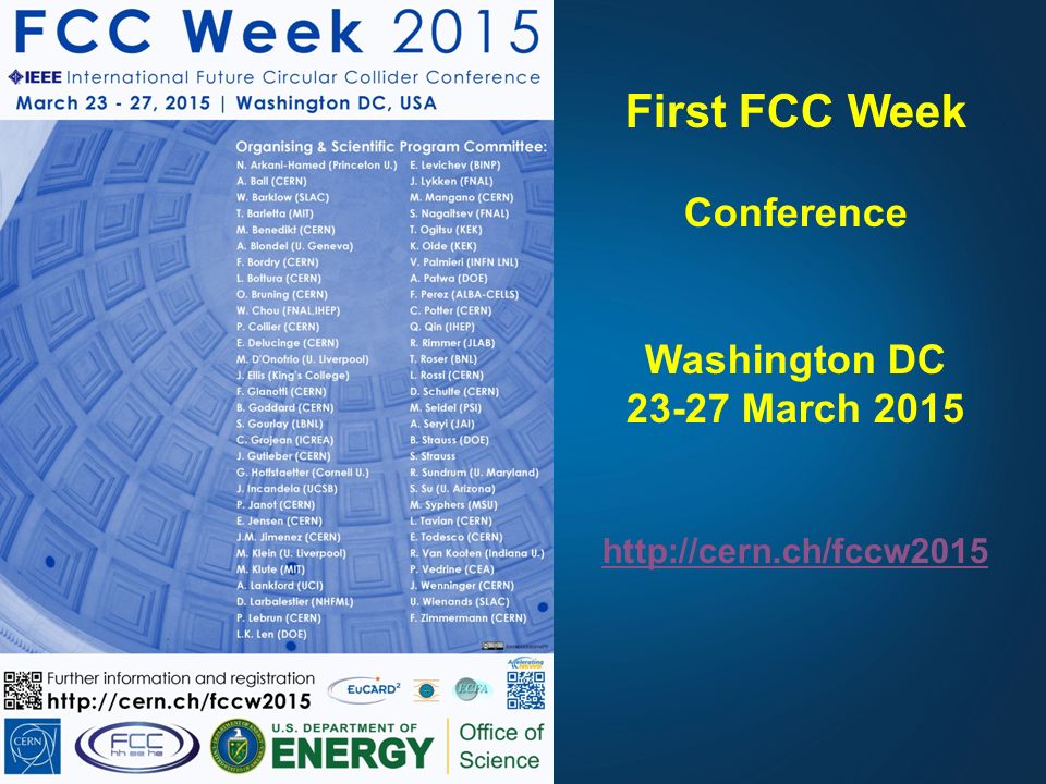
30
First FCC Week Conference Washington DC 23-27 March 2015
++...
31
First FCC Week, Washington DC 23-27 March 2015 – DRAFT SCHEDULE
hoping to see you there!

32
Conclusions There are strongly rising activities in energy-frontier circular colliders worldwide. The FCC collaboration is being formed with CERN as host laboratory, to conduct an international study for the design of Future Circular Colliders (FCC). Worldwide collaboration in physics, experiments and accelerators will be essential to advance and reach the goal of a CDR by 2018. FCC presents challenging R&D requirements in SC magnets, SRF and many other technical areas. Need to establish global collaboration and use all synergies to move forward!
. Worldwide collaboration in physics, experiments and accelerators will be essential to advance and reach the goal of a CDR by FCC presents challenging R&D requirements in SC magnets, SRF and many other technical areas. Need to establish global collaboration and use all synergies to move forward!")
Similar presentations


 Study>")
 Study - Status Michael Benedikt.>")


>")


>")


 bending magnet based on iron magnetization for 80-100 km lepton / hadron colliders Attilio Milanese, Lucio.>")

 accounting for all Particle Physics phenomena.>")
>")


