Download presentation
Presentation is loading. Please wait.

1
Three Phase Motors Maths

2
Poles and Speed

3
Power input to the Rotor
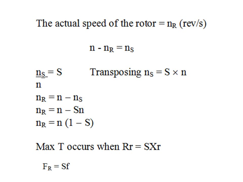
S = slip, either % or pu n = Synchronous speed (the speed the rotating mag flux rotates at and the speed the rotor is trying to get to. (rps or Hz) nR = Rotor speed. (rps or Hz) nS = Slip speed (rps or Hz) T = torque (Nm) FR = Frequency of the rotor currents. (Hz) F = supply frequency (Hz) p = No of pairs of poles P = Power (W) ER = Rotor emf at standstill (V) RR = Rotor resistance (Ω) XR = Rotor reactance (Ω)
 nR = Rotor speed. (rps or Hz) nS = Slip speed (rps or Hz) T = torque (Nm) FR = Frequency of the rotor currents. (Hz) F = supply frequency (Hz) p = No of pairs of poles. P = Power (W) ER = Rotor emf at standstill (V) RR = Rotor resistance (Ω) XR = Rotor reactance (Ω)")
5
Power developed by the rotor = 2nRT

8
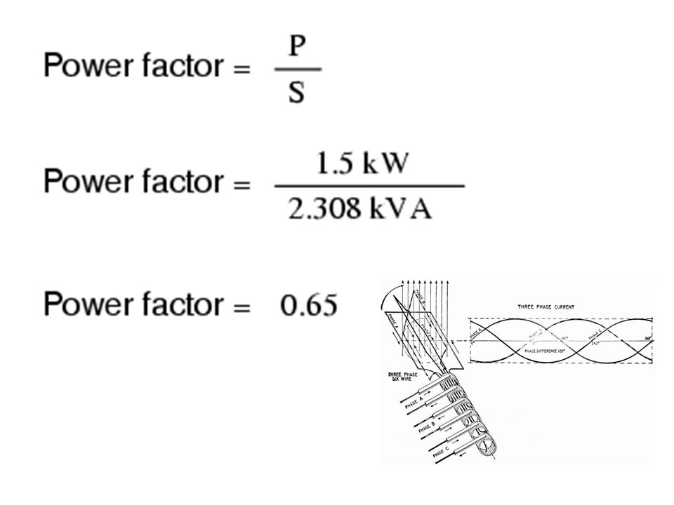
Power Factor It is common to define the Power Factor – PF
- as the cosine of the phase angle between voltage and current - or the "cosφ". PF = cos φ where PF = power factor φ = phase angle between voltage and current

10
The power factor defined by IEEE and IEC is the ratio between the applied active (true) power - and the apparent power, and can in general be expressed as: PF = P / S where PF = power factor P = active (true or real) power (Watts) S = apparent power (VA, volts amps)
 power (Watts) S = apparent power (VA, volts amps)")
11
Example - Power Factor A industrial plant draws 200 A at 400 V and the supply transformer and backup UPS is rated 200 A × 400 V = 80 kVA. If the power factor - PF - of the loads is only only kVA × 0.7 = 56 kW

12
What is the PF issue? Any power factor less than 1 means that the circuit's wiring has to carry more current than what would be necessary with zero reactance in the circuit to deliver the same amount of (true) power to the resistive load
 power to the resistive load.")
13
A low power factor is expensive and inefficient and some utility companies may charge additional fees when the power factor is less than 0.95. A low power factor will reduce the electrical system's distribution capacity by increasing the current flow and causing voltage drops.

14
"Leading" or "Lagging" Power Factors
Power factors are usually stated as "leading" or "lagging" to show the sign of the phase angle. With a purely resistive load current and voltage changes polarity in step and the power factor will be 1. Electrical energy flows in a single direction across the network in each cycle. Inductive loads - transformers, motors and wound coils - consumes reactive power with current waveform lagging the voltage. Capacitive loads - capacitor banks or buried cables - generates reactive power with current phase leading the voltage.

Similar presentations