Download presentation
Presentation is loading. Please wait.

1
X-Ray Diffraction By Cade Grigsby

2
What can X-ray diffraction tell us?
Structure Bonds Length Type Arrangement Geometry of crystal Picture Electron density map Diffraction Angle Intensity

3
From X-Rays to Structure
"X ray diffraction" by Thomas Splettstoesser ( - own work; the public domain image Myoglobindiffraction.png [1] was used; the other images were rendered with PyMol ( based on PDB id 1MBO. Licensed under CC BY-SA 3.0 via Wikimedia Commons -

4
X-Rays Short wavelength High frequency High energy 0.01 nm to 10 nm
30 petahertz (3.0E16) to 30 exahertz (3.0E19) High energy 100 eV to 100 keV Excites core electrons Ionizing radiation Deep penetration
 to 30 exahertz (3.0E19) High energy. 100 eV to 100 keV. Excites core electrons. Ionizing radiation. Deep penetration.")
5
Discovery of X-Rays Wilhelm Conrad Rӧntgan Cathode ray tube
Discovered in 1895 Nobel prize in physics 1901 Cathode ray tube Lit up fluorescent screen First X-ray image

6
X-Rays on EM Spectrum

7
Production of X-Rays Tungsten filament emits electron beam at target metal Cu or Mo Beam excites core electrons of target 1s electrons ionized X-rays emitted as higher level electrons fall Higher atomic number means higher energy X-rays

8
Ejection of electron

9
Other mechanism for x-rays
High energy electron slowed as it approaches nucleus Energy lost in ‘braking’ process released as x-ray photon

10
X-Ray Tube

11
Diffraction of Light Light bends passing edge of object
Effect of opening width on bending Interference creates dark and light spots Constructive Destructive

12
Effect of slit width

13
Single-slit diffraction

14
Double-slit experiment
Light is diffracted Slit width approximately equal to wavelength Diffraction pattern Wave interference Constructive Destructive

15
Diffraction Patterns Single-slit diffraction Double-slit diffraction
Constructive interference Destructive interference Double-slit diffraction What happens with multi-slit diffraction?

16
Multi-slit diffraction

17
The Problem with X-Rays
Electromagnetic waves diffract Early experiments could not diffract X-rays Wavelength too small New method for diffracting x-rays

18
The Solution Diffraction occurs when slit equals wavelength
X-ray wavelength equal to size of atom Use crystal lattice structure to diffract Diffraction pattern obtained

19
Evidence of Diffraction
Max von Laue, Walter Friedrich, and Paul Knipping in 1912 Pass X-rays through CuSO4 crystal and collect image on photographic plate Known as X-Ray Crystallography

20
Bragg’s Law William Lawrence Bragg and William Henry Bragg
2dsin(Θ) = nλ Nobel Prize in Physics 1915
 = nλ. Nobel Prize in Physics")
21
Single crystal X-Ray diffraction

22
Power Diffraction

23
Powder Analysis

24
First X-Ray Diffraction Pattern
Interference pattern White dots show constructive interference Dark space destructive interference Intensity of light Amount of interference Relates to amplitude and phase of X-rays

25
Mechanism of Diffraction
X-rays interact with core electrons Scatter photons Light diffracted at specific angles

26
Why diffraction points at specific angles?
Angle of diffraction decreases as distance of planes increases Reciprocal relationship Diffraction point distance from center decreases as distance between planes increases

27
Patterns in Patterns Patterns of in benzene
Diffraction spots perpendicular to planes

28
Greater Plane Distance

29
Along Planes of Symmetry

30
Other Scattering

31
Explained with Waves

32
Greater distance between planes
Increase distance of planes Light goes in phase again 5.0 cm distance between planes 45o angle of diffraction from the horizontal

33
Smaller Distance between Planes
Higher angle of diffraction Planes 2.0 cm apart Angle 60o

34
Crystal Structure

35
Other Compounds Rosalind Franklin B-form DNA
X-Ray cystallographer B-form DNA Dark spots areas of constructive interferance Strong bands top and bottom Base stacking Small distance between planes, high angle

36
Reason for Pattern

37
Further Reasoning http://doublehelix.me/about/

38
Watson and Crick Shown diffraction pattern by colleague of Franklin, Maurice Wilkins Recognized pattern Worked with helical proteins

39
What does this tell us? Interactions with core electrons
Electron density Location of atoms Center of electron density Type of bonds Specific angles of diffraction Unique to specific crystals Miller indices

40
From X-Rays to Structure
"X ray diffraction" by Thomas Splettstoesser ( - own work; the public domain image Myoglobindiffraction.png [1] was used; the other images were rendered with PyMol ( based on PDB id 1MBO. Licensed under CC BY-SA 3.0 via Wikimedia Commons -

41
The Transition How do you get from a diffraction pattern to an electron density map? Computer programs

42
Detection of Angles of Diffraction
Diffractometers equipped with X-ray counters Angle relative to crystal Intensity of X-rays Modern instruments coupled with CCD detectors Each element has specific angles of diffraction

43
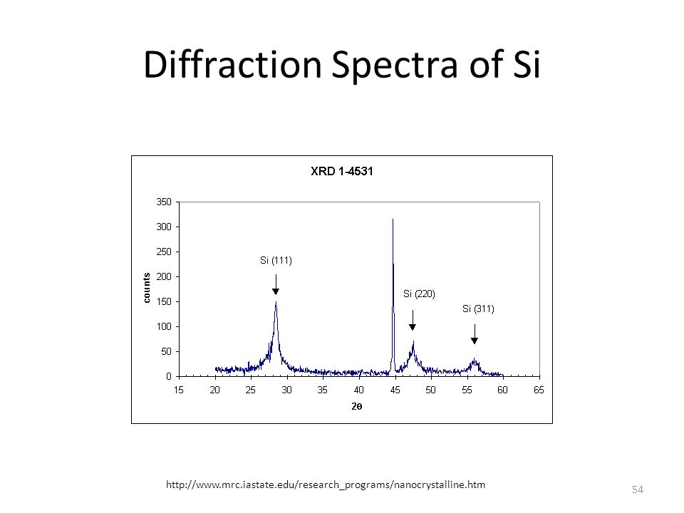
Diffraction Spectra of Si

44
Diffraction of NaCl

45
Zinc Oxide Nano particles

46
Miller Indices Describes planes in a crystal Assign origin point
H, K, and L Written (hkl) Each distance written as its reciprocal
 Each distance written as its reciprocal.")
47
More Miller Indices

48
Determination of Lattice Structure
‘a’ is lattice constant of cubic crystal ‘h’, ‘k’, and ‘l’ are the Miller indices of Bragg plane Without computer Trial and error

49
Body Centered Cube (BCC)
h+k+l must equal an odd number Fe and W crystals

50
Iron Crystal

51
Face Centered Cube (FCC)
h, k, l must be all odd or all even values Cu, Al, NaCl crystals

52
Diffraction of NaCl

53
Diamond FCC Atoms quarter of diagonal length apart h+k+l = 4n
Values must be all even or all odd Si crystals

54
Diffraction Spectra of Si
55
Electron Density Map Constructed from diffraction pattern
Slice of the crystal Can be used to determine information on bonds Length and type

56
Modern Electron Density Mapping

57
Other uses

58
Analysis of Electron Density Map
Contour rings One represents 1e/Å Electronegative atoms More contour rings Determination of bonds Shortest are double bonds Intermediate bonds are resonance Longest bonds are single bonds No hydrogens Too few electrons

59
Measuring Bonds Interpretation by comparison
Measure from center of contours Aromatic C—C bonds 1.5 cm Double C=O bond 1.5 cm Double C=C bond 1.1 cm Single C—C and C—O bonds 1.9 cm Computers can also perform calculations

60
Conclusion Structure Diffraction pattern Identification of atoms Bonds
Miller Indices and computer programs Crystal geometry Electron density map Diffraction pattern Arrangement based on plane distance Diffraction angle Identification of atoms Specific diffraction angle Rough estimate with electron density Bonds Length Type

61
Questions?

Similar presentations
 K = Hot filament cathode A = Tungsten anode U h = Heater Voltage (e.g. 12V) U a = Accelerating.>")


>")

 Pure metal target (Cu) Electrons remover inner-shell electrons from target. Other electrons “fall”>")


>")


 10 -15 10 -12 10 -9 10 -6 10 -3 1.010 3 10 6 Gamma Rays X-rays UVIR Micro TVFMAM Long Radio.>")
 We also looked at internal ordering of atoms in 3-D structure (230 space.>")


