Download presentation
Presentation is loading. Please wait.

1
Definitions Electromagnetic Compatibility : (EMC) The capability of electrical and electronic systems, equipment, and devices to operate in their intended electromagnetic environment within a defined margin of safety and at design levels or performance without suffering or causing unacceptable degradation as a result of electromagnetic interference [American National Standards Institute (ANSI) C64.14-1992)].
![Definitions Electromagnetic Compatibility : (EMC) The capability of electrical and electronic systems, equipment, and devices to operate in their intended electromagnetic environment within a defined margin of safety and at design levels or performance without suffering or causing unacceptable degradation as a result of electromagnetic interference [American National Standards Institute (ANSI) C )].](http://images.slideplayer.com/26/8807598/slides/slide_1.jpg "Definitions Electromagnetic Compatibility : (EMC) The capability of electrical and electronic systems, equipment, and devices to operate in their intended electromagnetic environment within a defined margin of safety and at design levels or performance without suffering or causing unacceptable degradation as a result of electromagnetic interference [American National Standards Institute (ANSI) C )].")
2
Electromagnetic Interference : (EMI) : The process by which disruptive electromagnetic (EM) energy is transmitted from one electronic device to another via radiated or conducted paths (or both). In common usage, the term refers particularly to RF signals; however, EMI is observed throughout the EM spectrum.

3
Radio Frequency. (RF) A frequency range containing coherent EM radiation of energy useful for communication purposes—roughly the range from 9 kHz to 300 GHz. This energy may be emitted as a by-product of an electronic device’s operation. Radio frequency is emitted through two basic mechanisms
 A frequency range containing coherent EM radiation of energy useful for communication purposes—roughly the range from 9 kHz to 300 GHz. This energy may be emitted as a by-product of an electronic device’s operation. Radio frequency is emitted through two basic mechanisms.")
4
Radiated Emissions. The component of RF energy that is emitted through a medium as an EM field. Although RF energy is usually emitted through free space, other modes of field transmission may be present. Conducted Emissions. The component of RF energy that is emitted through a medium as a propagating wave generally through a wire or interconnect cables. Line-conducted interference (LCI) refers to RF energy in a power cord or alternating- current (AC) mains input cable. Conducted signals propagate as conducted waves.
 refers to RF energy in a power cord or alternating- current (AC) mains input cable. Conducted signals propagate as conducted waves..")
5
Susceptibility. A relative measure of a device or a system’s propensity to be disrupted or damaged by EMI exposure to an incident field. It is the lack of immunity. Immunity. A relative measure of a device or system’s ability to withstand EMI exposure while maintaining a predefined performance level.

6
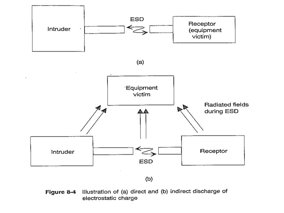
Electrostatic Discharge (ESD). A transfer of electric charge between bodies of different electrostatic potential in proximity or through direct contact. This definition is observed as a high- voltage pulse that may cause damage or loss of functionality to susceptible devices.

7
Radiated Immunity. A product’s relative ability to withstand EM energy that arrives via free-space propagation. Conducted Immunity. A product’s relative ability to withstand EM energy that penetrates through external cables, power cords, and input–output (I/O) interconnects.
 interconnects..")
8
Containment. A process whereby RF energy is prevented from exiting an enclosure, generally by shielding a product within a metal enclosure (Faraday cage or Gaussian structure) or by using a plastic housing with RF conductive coating. Reciprocally, we can also speak of containment in the inverse, as exclusion—preventing RF energy from entering the enclosure. Suppression. The process of reducing or eliminating RF energy that exists without relying on a secondary method, such as a metal housing or chassis. Suppression may include shielding and filtering as well.
 or by using a plastic housing with RF conductive coating. Reciprocally, we can also speak of containment in the inverse, as exclusion—preventing RF energy from entering the enclosure. Suppression. The process of reducing or eliminating RF energy that exists without relying on a secondary method, such as a metal housing or chassis. Suppression may include shielding and filtering as well..")
9
There are five major considerations when performing EMC analysis on a product or design [1]: 1. Frequency. Where in the frequency spectrum is the problem observed? 2. Amplitude. How strong is the source energy level and how great is its potential to cause harmful interference? 3. Time. Is the problem continuous (periodic signals) or does it exist only during certain cycles of operation (e.g., disk drive write operation or network burst transmission)? 4. Impedance. What is the impedance of both the source and receptor units and the impedance of the transfer mechanism (related to separation distance, which affects wave impedance) between the two 5. Dimensions. What are the physical dimensions of the emitting device (or device groups) that cause emissions to be observed? The RF currents will produce EM fields that will exit an enclosure through chassis leaks that equal significant fractions of a wavelength or significant fractions of a “rise time distance.”
![There are five major considerations when performing EMC analysis on a product or design [1]: 1.](http://images.slideplayer.com/26/8807598/slides/slide_9.jpg "Frequency. Where in the frequency spectrum is the problem observed. 2. Amplitude. How strong is the source energy level and how great is its potential to cause harmful interference. 3. Time. Is the problem continuous (periodic signals) or does it exist only during certain cycles of operation (e.g., disk drive write operation or network burst transmission). 4. Impedance. What is the impedance of both the source and receptor units and the impedance of the transfer mechanism (related to separation distance, which affects wave impedance) between the two 5. Dimensions. What are the physical dimensions of the emitting device (or device groups) that cause emissions to be observed. The RF currents will produce EM fields that will exit an enclosure through chassis leaks that equal significant fractions of a wavelength or significant fractions of a rise time distance. .")
10
Problems during emission testing Equipment Setup and Environment. Most products require use of support (auxiliary) systems to ensure functionality. Auxiliary equipment may be located directly adjacent to the EUT or be remote. If remote, routing cables between systems play an important part in the setup. Cables may be routed under the floor or overhead. The following problems commonly happen during equipment setup:
 systems to ensure functionality. Auxiliary equipment may be located directly adjacent to the EUT or be remote. If remote, routing cables between systems play an important part in the setup. Cables may be routed under the floor or overhead. The following problems commonly happen during equipment setup:.")
11
1. Ambient Assessment. 2. Mismatch and VSWR Errors. 3. Background Noise within Instrumentation Setup.

12
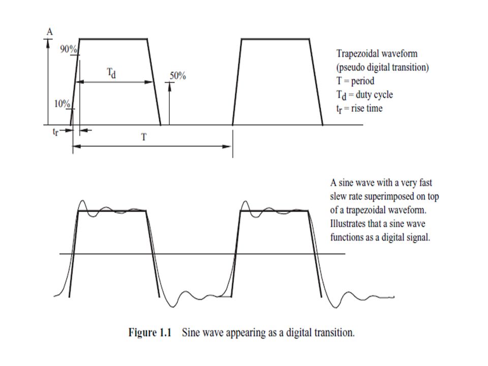
TIME-DOMAIN VERSUS FREQUENCY-DOMAIN ANALYSIS It is common for digital design engineers to think in terms of a time frame or in the time domain. Electromagnetic interference is generally viewed as a frequency spectrum or in the frequency domain. Radio- frequency energy is typically a periodic wave front that propagates through various media. Different wavelengths of a sine wave are recorded as EMI for those products that are not designed to be intentional radiators. It is difficult to understand an EMI problem in the time domain alone. All digital transitions (when viewed in the time domain) produce a spectral distribution of RF energy (frequency domain).
 produce a spectral distribution of RF energy (frequency domain)..")
13
Conversely, a series of fast slew rate sine waves appear as a digital transition pulse. In other words, a time-domain waveform may be defined as a set of sine waves and may be combined graphically or mathematically, but not physically, into a time waveform.

15
Coupling is a significant aspect of signal propagation. When performing testing and troubleshooting, we need to understand the types of coupling we deal with and how they affect overall system operation.. Understanding the 2 modes of current flow.

16
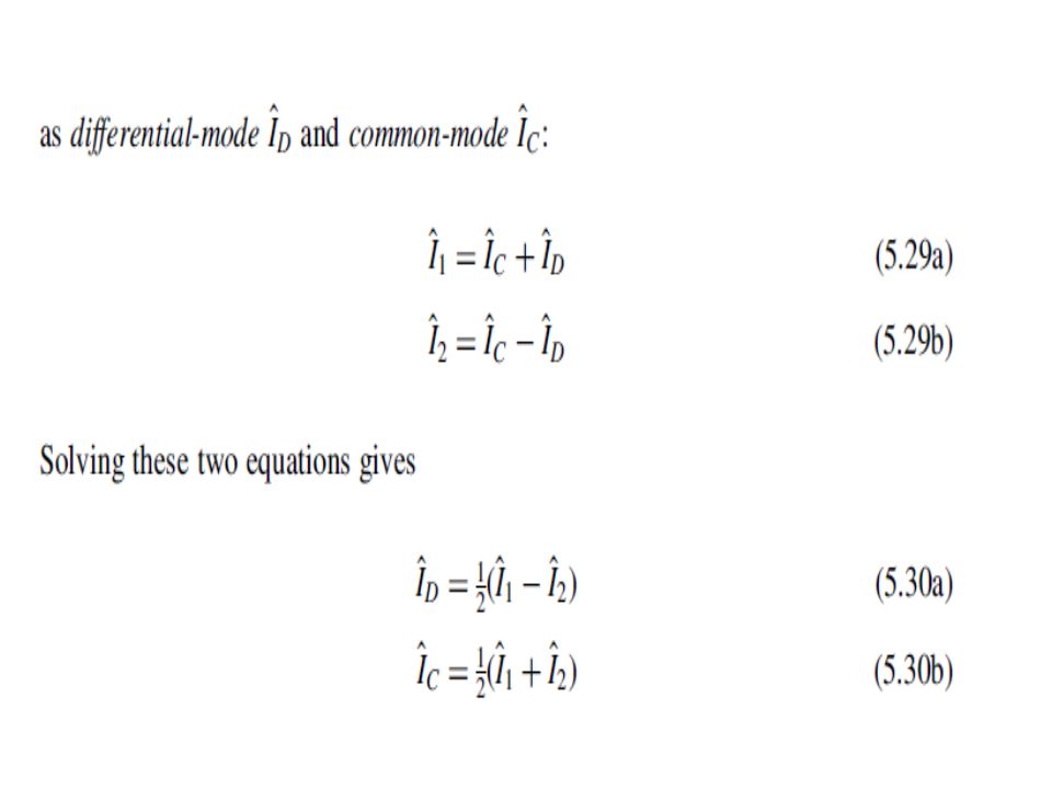
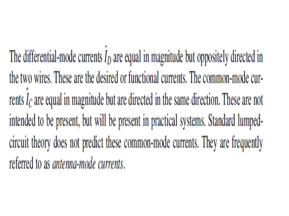
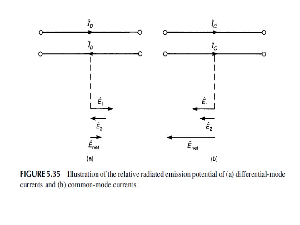
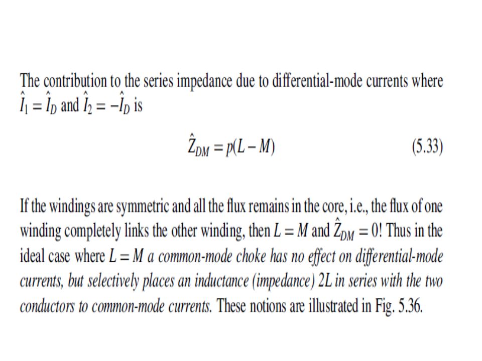
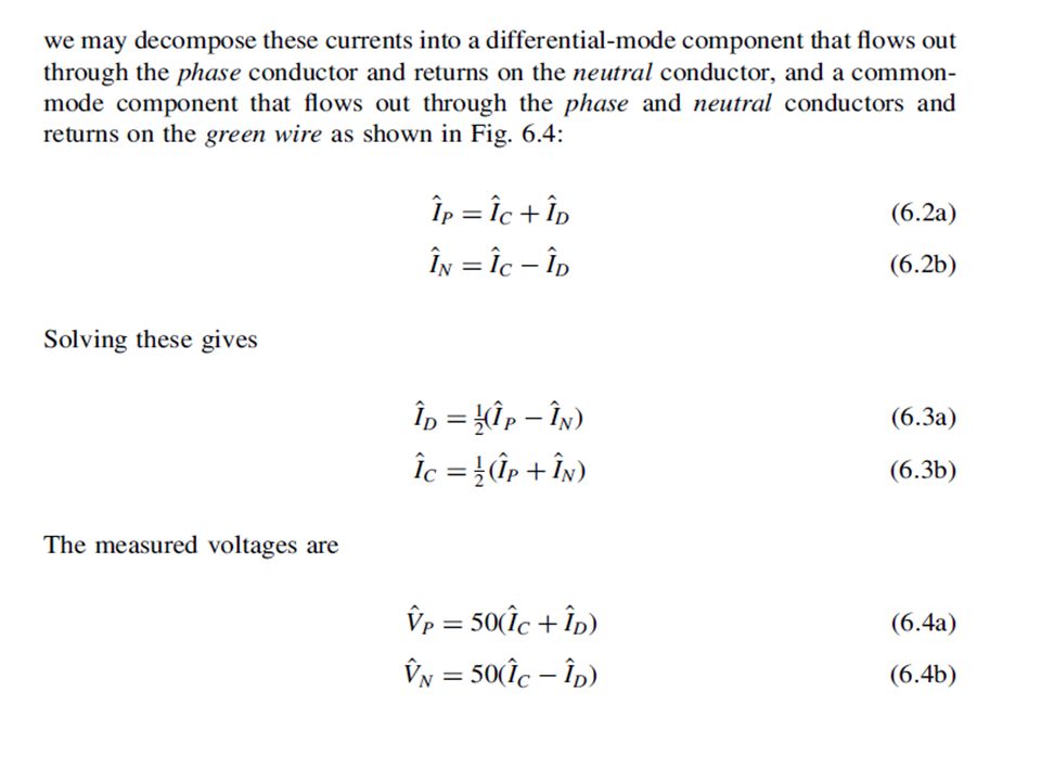
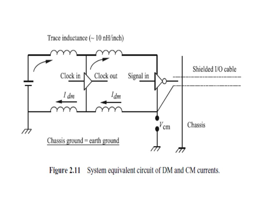
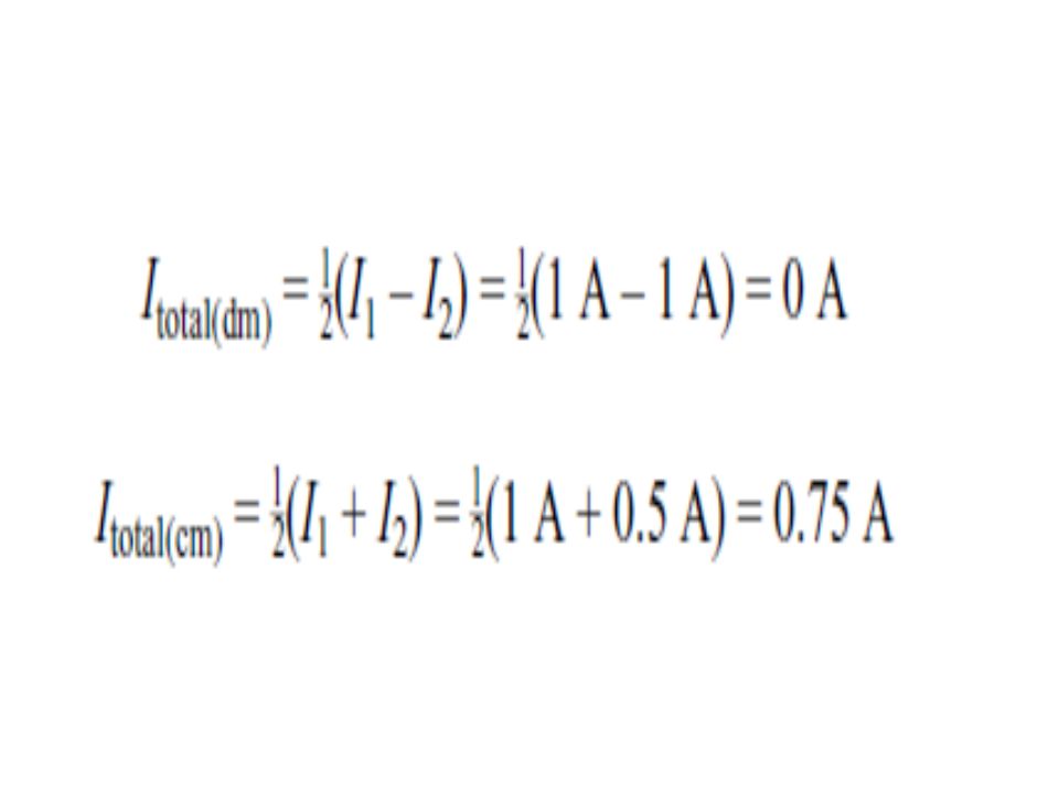
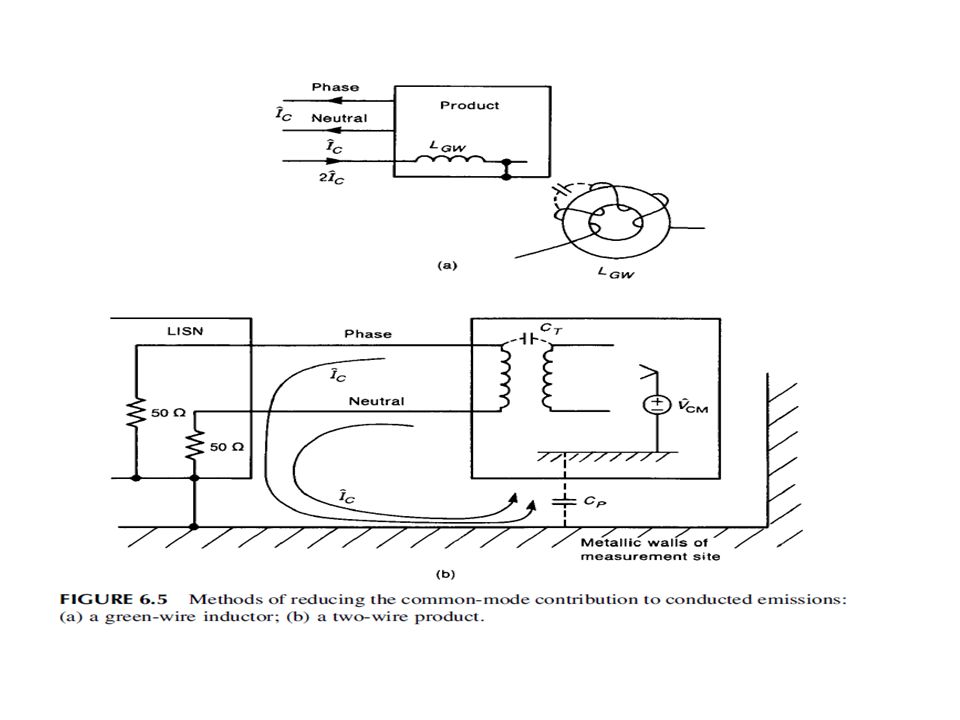
Differential and Common-mode. For almost every type of communication, differential mode is desired; however, common mode is generated due to various reasons. Electromagnetic compatibility problems are mainly common mode.

20
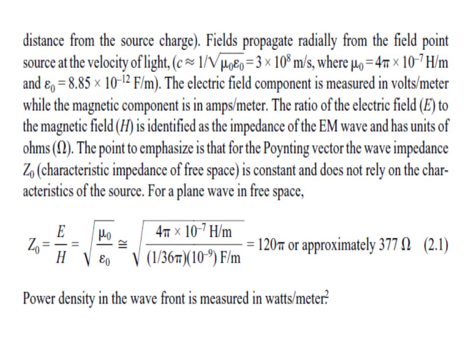
The Poynting vector is a convenient method for expressing the direction and the power of the EM wave with units of watts per square meter (W/m2). In the far field, both electric and magnetic field components are at right angles to each other and perpendicular to the direction of propagation. There is no such thing as an electric wave or a magnetic wave by itself.

23
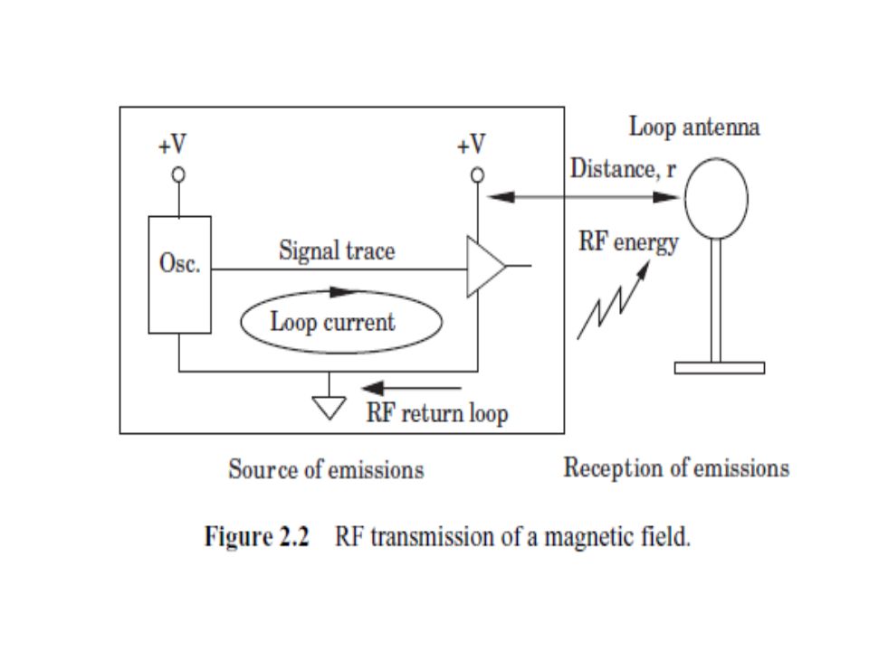
1. Current Amplitude in Loop. 2. Orientation of Source Loop Antenna Relative to Device Under Test. 3. Size of Loop. 4. Distance.

25
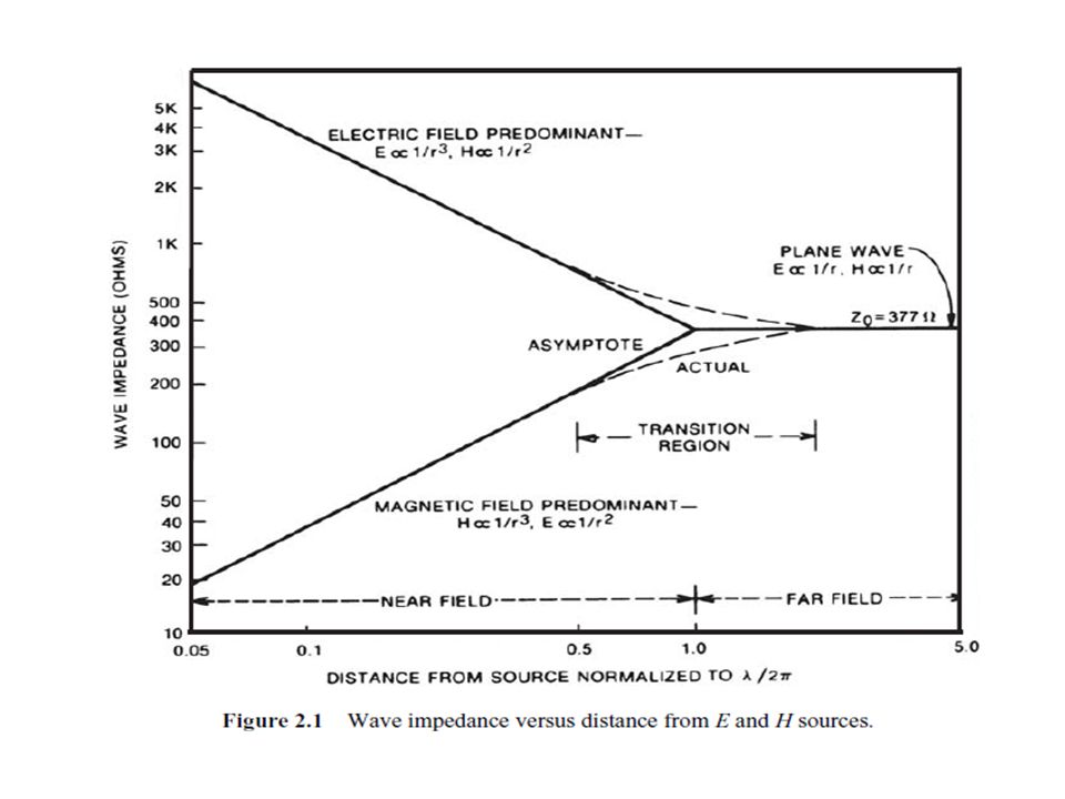
The fields created by an electric source are a function of four variables: 1.Current Amplitude in Dipole. The fields created are proportional to the amount of current flowing in the dipole. 2. Orientation of Dipole Relative to Measuring Device. This is equivalent to the magnetic source variable described earlier. 3. Size of Dipole. Fields created are proportional to the length of the current element. This is true if the length of the trace is a small fraction of a wavelength. 4. Distance. Electric and magnetic fields are related to each other. Both field strengths fall off with increasing distance. In the far field, the behavior is similar to that of the loop source. When we move in close to the point source, both magnetic and electric fields have a greater dependence on distance from the source.

26
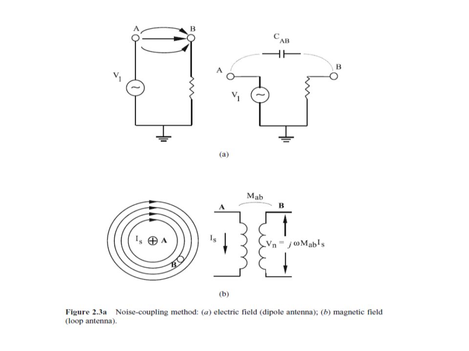
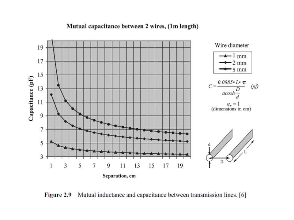
Propagation of RF energy, both electric and magnetic fields, can be represented as equivalent component models that help describe their propagation mode with an antenna structure as the visual display. A time-varying electric field between two conductors can be represented as a capacitor configuration (dipole antenna). A time-varying magnetic field between these same two conductors is represented by mutual inductance (loop antenna) Figures 2.3a,b illustrate these two coupling configurations
. A time-varying magnetic field between these same two conductors is represented by mutual inductance (loop antenna) Figures 2.3a,b illustrate these two coupling configurations.")
30
Common Impedance coupling Common-impedance coupling develops when both source and victim share a transmission path through a common impedance. The most frequent example of common-impedance coupling is found in a shared reference connection between modules. This shared reference is usually a return wire within a cable assembly or in the earth ground reference of the power distribution system. Figure 2.5 illustrates two means of common- impedance coupling in a simplified manner

34
Electromagnetic Field Coupling Electromagnetic field coupling is a combination of both magnetic and electric fields affecting a circuit simultaneously. Depending on the distance between source and receptor, the electric field (E) and magnetic field (H) may be operatively dominant, depending on whether we are in the near field or far field. This is the most common transfer mechanism observed by measurement with an antenna.
 and magnetic field (H) may be operatively dominant, depending on whether we are in the near field or far field. This is the most common transfer mechanism observed by measurement with an antenna..")
36
Conductive Coupling The process of conduction between a source and receptor involves transference of an EM field through a metallic interconnect. Interference energy can be carried between power supply lines and signal transmission cables. For example, interference between systems plugged into the same electrical outlet may share undesired RF energy, causing harmful interference or disruption of functionality. Conductive transfer can occur through common- impedance coupling. This happens when both the noise source and susceptible circuits are connected by mutual impedance.

45
Radiated & Conducted coupling combined :

79
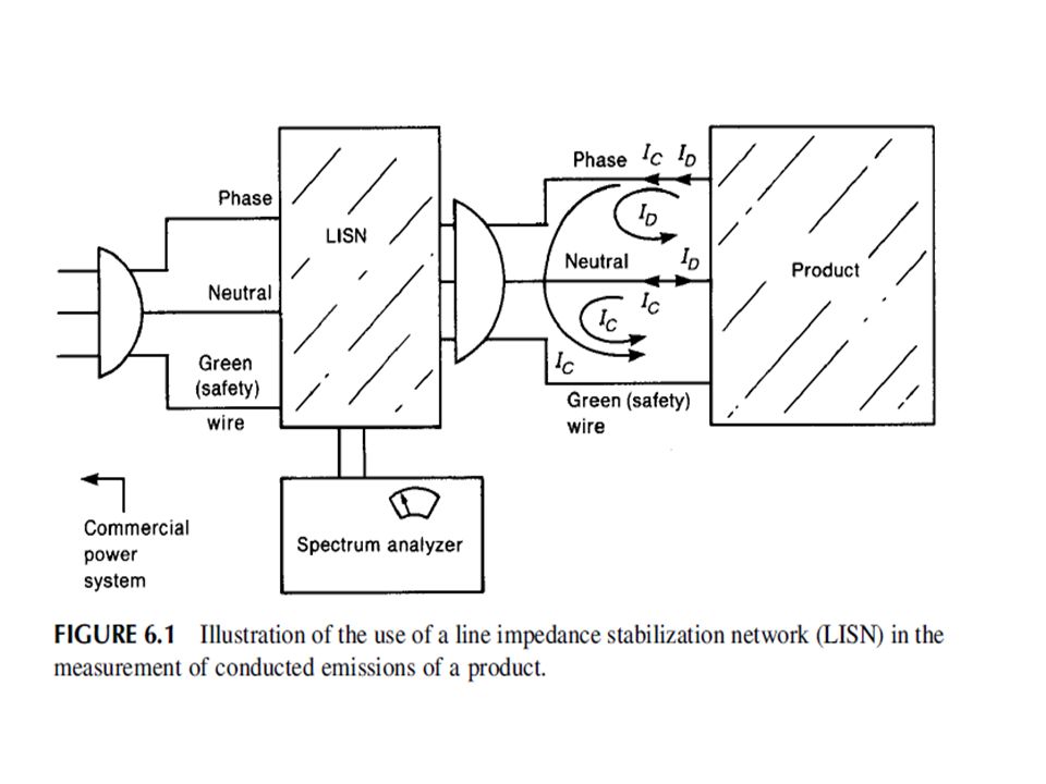
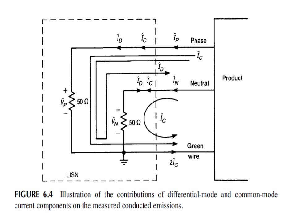
Conducted Emissions

81
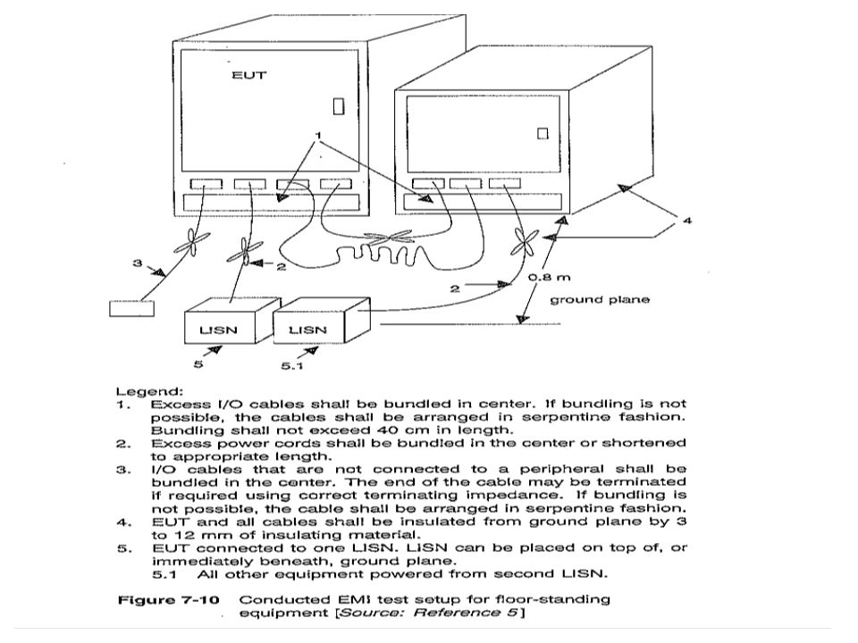
second objective of the LISN—to block conducted emissions that are not due to the product being tested so that only the conducted emissions of the product are measured. This is the first objective of the LISN—to present a constant impedance to the product’s power cord outlet over the frequency range of the conducted emission test.

89
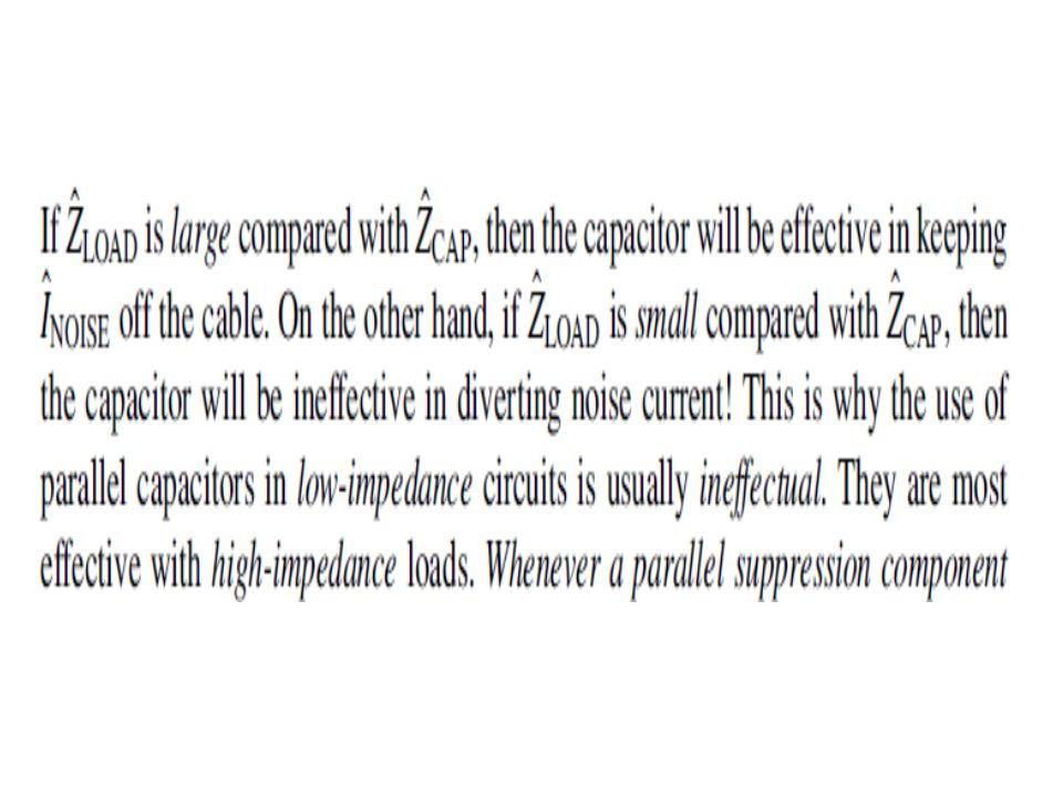
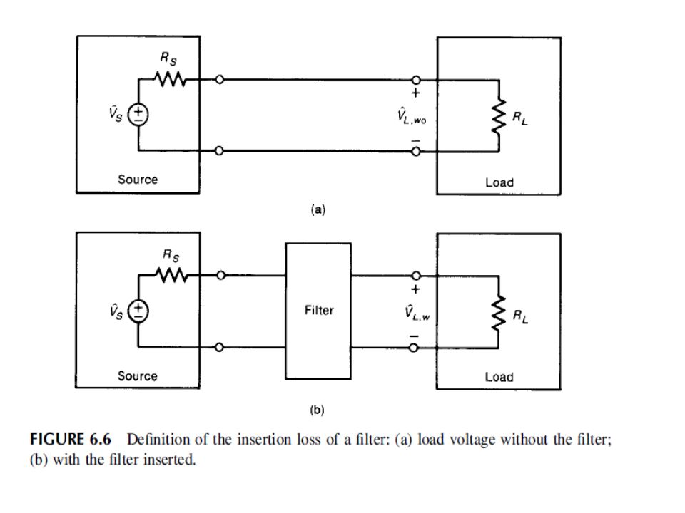
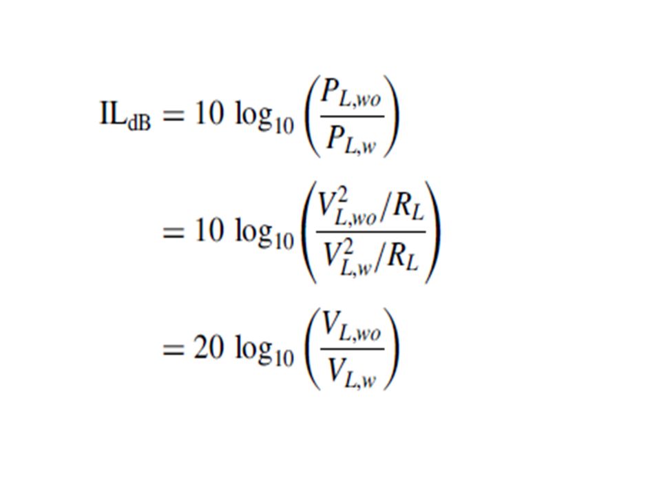
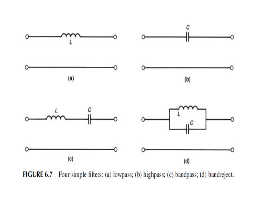
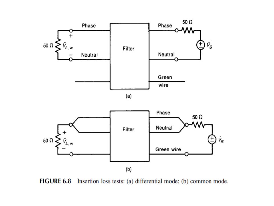
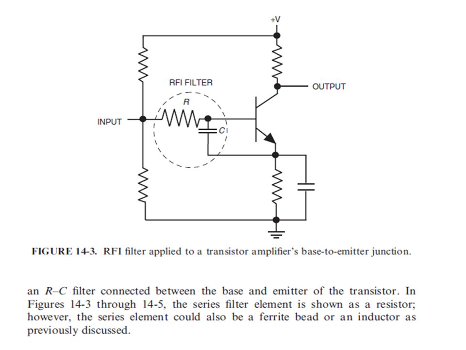
Power supply filters Filters are typically characterized by their insertion loss (IL), which is typically stated in dB. Consider the problem of supplying a signal to a load as shown in Fig. 6.6a. A filter is inserted between the source and the load in order to prevent certain frequency components of the source from reaching the load, as shown in Fig. 6.6b.

96
RF & Transient Immunity

97
Conducted rf immunity standards for commercial products typically require that the product operate properly without degradation (performance criteria A) when an rf voltage of 3 V (for residential/commercial products) or 10 V (for industrial equipment), 80% amplitude modulation (AM) from 150 kHz to 80 MHz is coupled common-mode into the alternating current (ac) power cables (EN 61000-6-1, 2007). The test also must be applied to signal cables, to direct current (dc) power cables and ground conductors if they are over 3 m in length. The voltage is applied as a common-mode voltage to the cable conductors.
 power cables and ground conductors if they are over 3 m in length. The voltage is applied as a common-mode voltage to the cable conductors..")
98
Radiated rf immunity standards for commercial products typically require that the product operate properly without degradation (performance criteria A) when exposed to an electric field of either 3 V/m (for residential/commercial products) or 10 V/m (for industrial equipment), 80% AM modulated from 80 to 1000 MHz. Higher field strengths, up to 200 V/m, are applicable for automotive and military products.

115
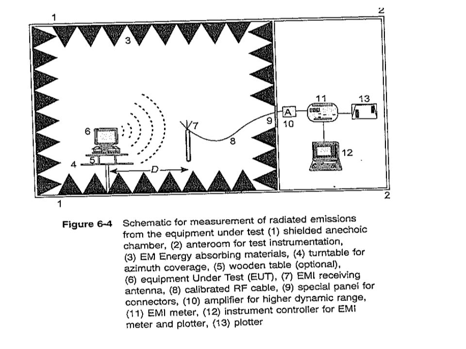
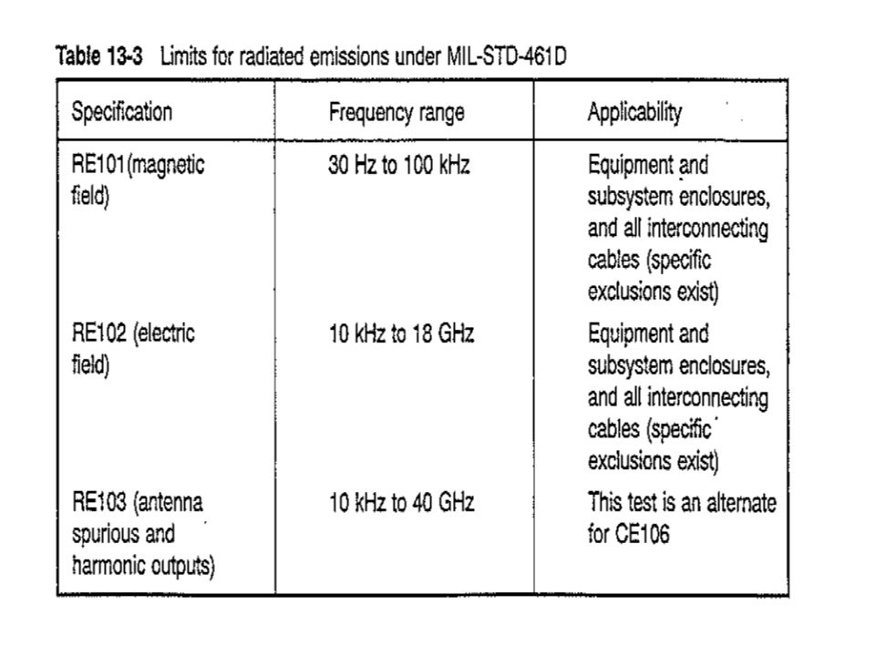
RE Can be done in OATS. Can be carried out in a shielded anechoic chamber. Dipole antennas & other broad band antennas like log-periodic, biconical horn can be used. Vertical and horizontal polarization. All test equipment in ante-room.

117
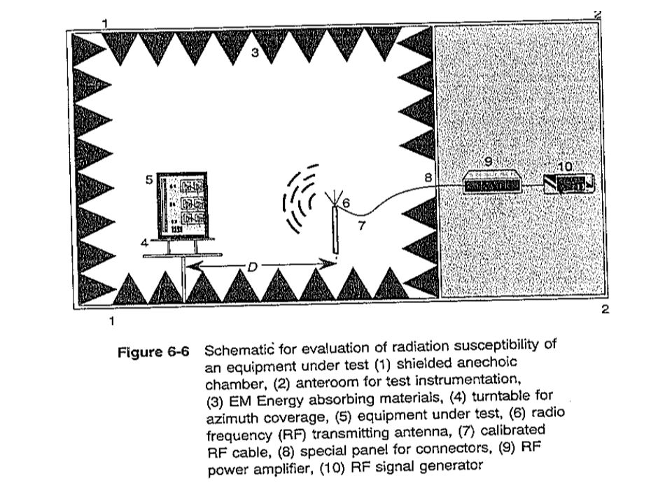
RS Use of dipole and other broad band antennas. Test instrumentation is ante room.

119
CE CE…..Evaluation. Always with LISN.

122
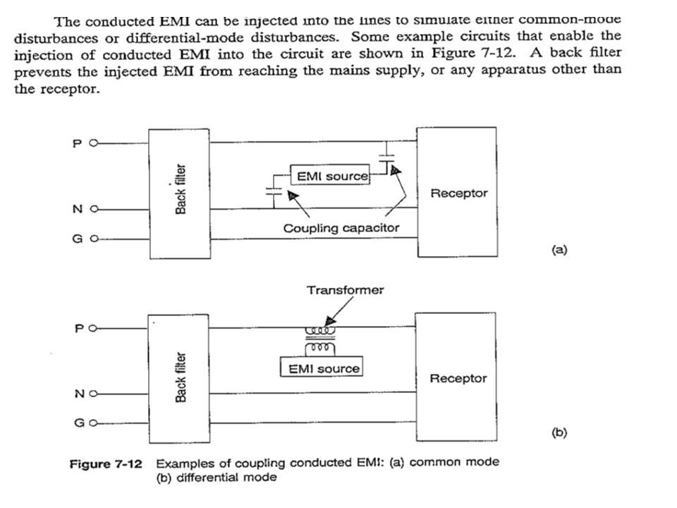
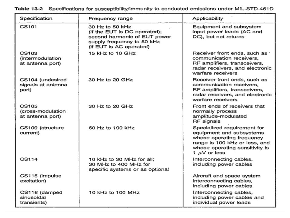
CS Injecting CM disturbance. Injecting DM disturbance. Backfilter to prevent injected EMI from reaching the power source.

124
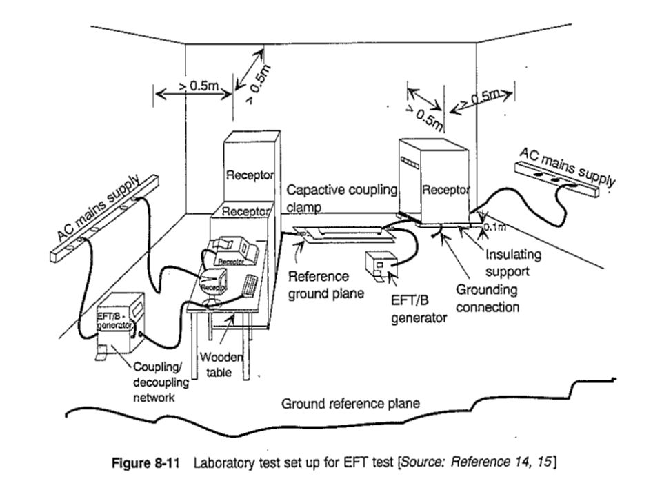
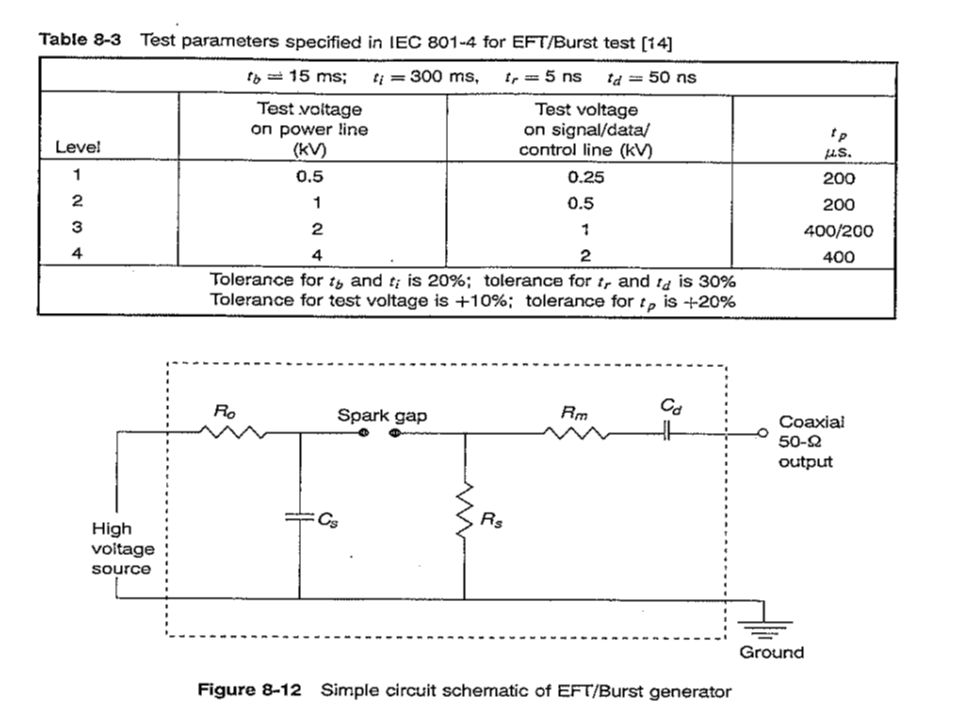
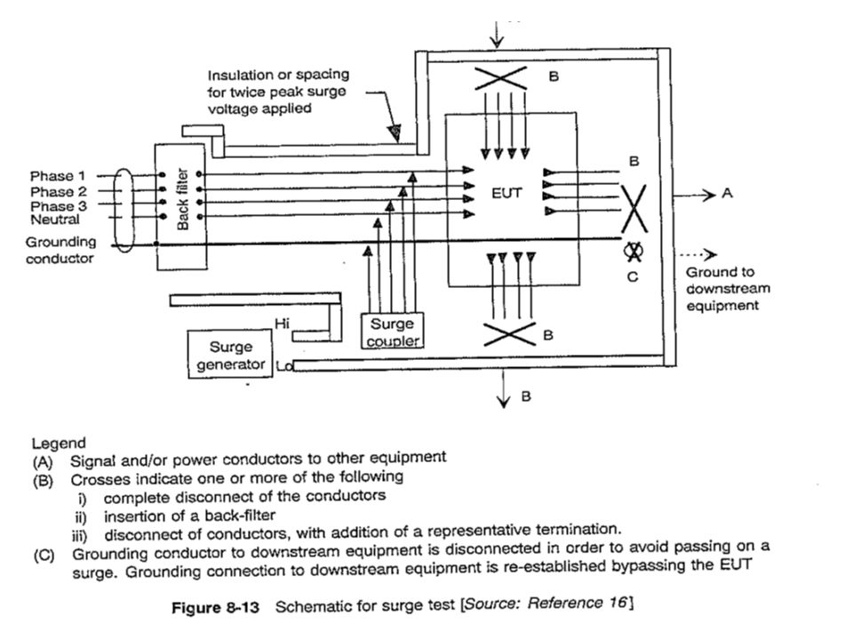
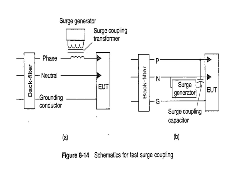
Pulsed Interference Immunity Transients. ESD………On the equipment. EFT ………On all A.C.& D.C.power lines, signal lines, control lines, I/O ports. Lightning Surges…..On A.C and D.C power lines.

Similar presentations


>")

.>")


/Signal Integrity Members: Aaron Cook, Yatharth Khullar, Xi Wang, Ruofei.>")