Download presentation
Presentation is loading. Please wait.

1
DAQ Hardware status - overview R. Stokstad DOM Main Board –Schedule (Minor) –Design (Przybylski) –Firmware (Stezelberger) –Testing (Goldschmidt) DOR Board (Sulanke) Master Clock Unit (Nygren, Sulanke) Time Calibration, Cable measurements (Stokstad, Sulanke, Hardtke) Individual presentations for the above to be in Mons proceedings
 –Design (Przybylski) –Firmware (Stezelberger) –Testing (Goldschmidt) DOR Board (Sulanke) Master Clock Unit (Nygren, Sulanke) Time Calibration, Cable measurements (Stokstad, Sulanke, Hardtke) Individual presentations for the above to be in Mons proceedings.")
2
Rev 2 board

3
Icecube DOM MB Status and Development April – Oct '03 –Rev 2 test and development (22 boards) Oct – Nov ’03 –Rev 3 fabrication and test (16 boards) Nov ’03 – Mar ’04 – Rev 4 fabrication and test (60 boards) March – June ’04 –Rev 5 for deployment (420 boards) Schedule
 Oct – Nov ’03 –Rev 3 fabrication and test (16 boards) Nov ’03 – Mar ’04 – Rev 4 fabrication and test (60 boards) March – June ’04 –Rev 5 for deployment (420 boards) Schedule")
4
October – November ‘03 First 4 cards due Oct 22, 12 more to follow 5 days after approval –Changes from Rev 2 address memory performance at temperature and signal quality issues –Testing at LBNL will include manual tests and STF testing –Temp cycling of bare and loaded boards +65, -40degC 10 cycles First 4 cards to UW 8 cards to UW, 8 cards to LBNL Rev 3 status

5
November – March ‘04 –Design modifications as indicated by Rev 3 tests and internal review –Final parts selection for reliability –60 cards to be fabricated –“Qualification test” at UW Longer term temperature tests String operation tests Some boards used for development at LBNL Rev 4 plans

6
Rev 5 plans Initial production review November ‘03 –Based on Rev 3 and Rev 4 tests –Earlier than usual to enable long-lead parts purchasing Production readiness review - January ‘04 –Based on initial Rev 4 tests –Qualification testing –Vendor qualifications –Fabrication process approval

7
Rev 5 Production (March – June ’04) Full production and Q/A procedures in place All parts as selected for reliability ATWD production run including qualification tests Any differences between Rev 4 and Rev 5 require formal Engineering Change Procedure and re-qualification testing Fabrication begins March ‘04 Testing begins April ’04 Delivery April - June ‘04
 Full production and Q/A procedures in place All parts as selected for reliability ATWD production run including qualification tests Any differences between Rev 4 and Rev 5 require formal Engineering Change Procedure and re-qualification testing Fabrication begins March ‘04 Testing begins April ’04 Delivery April - June ‘04")
8
EPXA4 Baseline (The larger FPGA) Hi-Reliability Part Substitutions –Primary Oscillator; Corning (Hi-Rel 2560A-0009) –High-Rel DC-DC Converter; Power-One brand Low impedance Power Distrib.to SDRAM 2 x 12 Channel ADCs vs. 1 x 8 Channel for monitoring Q/A Tests Added to Plan; Coupons on PCB Noise Related Layout Changes Fabrication procedure changes Some Changes made in Rev 3

9
DOMMB Block Diagram

10
Firmware CPLD (lowest level programmable logic device) Almost finished. Smallr changes needed for Rev 3 and to make the design more robust. FPGA –STF99% Done for testing –ConfigBoot Preliminary Versionminimal boot –IceBoot Preliminary Versionnormal boot –DOMAPP~50% Done for data taking For software development purposes the SFT FPGA can be used for the ConfigBoot and the IceBoot FPGAs

11
DOR card Firmware Status Production Status, Rev. 0 Planned Production, Rev. 1 Data Buffer SRAM 2 x 256Kx16 Cable Interface #1 Cable Interface #2 Cable Interface #3 Cable Interface #4 PCI-CorePCI-Core FLASH 1M x 8 Altera PLD EPM7064 ConfigJTAG Altera FPGA EP20K200E JTAG PCI Bus DOM 1..4 JTAG Clock 96 V DOM 5..8 Reload

12
DOR, DO M Readout card 12 ICECUBE Meeting, Mons October 2003 FPGA FLASHSRAM 96V DOM Power Clock & Time String port JTAG PLD Comm. ADC Comm. DAC Quad Cable Con. Comm. Rec. Power Switch

13
Production Status Rev. 0, 10 DORs running at : UW 2x, Bartol 1x, LBNL 7x 20 more in production now, ready in Dec. 2003 4 stay at DESY, 16 go to ? Planned Production, Rev. 1 Redesign ready in January first test in Feb., production of 60 if o.k. 60 ready in April 2004 60 DORs -> sufficient to control 480 DOMs

15
DOMMB Test Plan Select well functioning DOM MBs (including delay board) suitable for integration into DOMs to be deployed in IceCube/IceTop. For boards which are not well functioning, provide information to aid understanding, debugging and fixing. Provide some DOMMB characterization: optimum running parameters, etc. Be able to handle an expected “steady state” flow of 55 boards/week.

16
Initial Tests Visual inspection, Power to board Load “released” firmware and software in dedicated setup (1 board at a time) Get “boot prompt” and tests that cannot be done in DOR-based setup (if any) Multiple heating and cooling cycles (+65C to -40 C) to catch infant mortality cases. Boards powered and some testing during burn-in Power cycles during burn-in Full operational test at the end to identify bad boards. Burn-in

17
Master Clock Unit: Function Create and distribute stable 20 MHz source to all DOM Hubs in IceCube DAQ. –DOR cards mirror MCU time, calibrate DOMs Link “IceCube Time” to GPS time. Provide robust real-time time verification. –Motivation: detect any error condition in less than 1 sec

18
Master Clock Unit (MCU) Status Draft Requirements Document exists Specific Implementation proposals have been made by Sulanke and Przybylski. Plan is that Sulanke will design and fabricate this subsystem at DESY.

19
Time Calibration Tests Results using a waveform template Cross-talk measurements Cable stub asymmetry results

20
DOR DOM

21
Scope at DOR Scope at DOM

22
One-way time = 1/2 round trip time ONLY IF Symmetry in pulse generation and transmission Signal processing same at both ends Golden Rule of Time Calibration

23
DOR DOM DOR - DOM testDOR - DOR test DOR-DOR has same clock for transmitting and receiving DOR-DOM Asymmetry Test

25
V t t= V/( V/ t) Clock period 50 ns Time resolution < 5 ns Rise time ~400 ns -> linear algorithm should be OK
 Clock period 50 ns Time resolution < 5 ns Rise time ~400 ns -> linear algorithm should be OK")
26
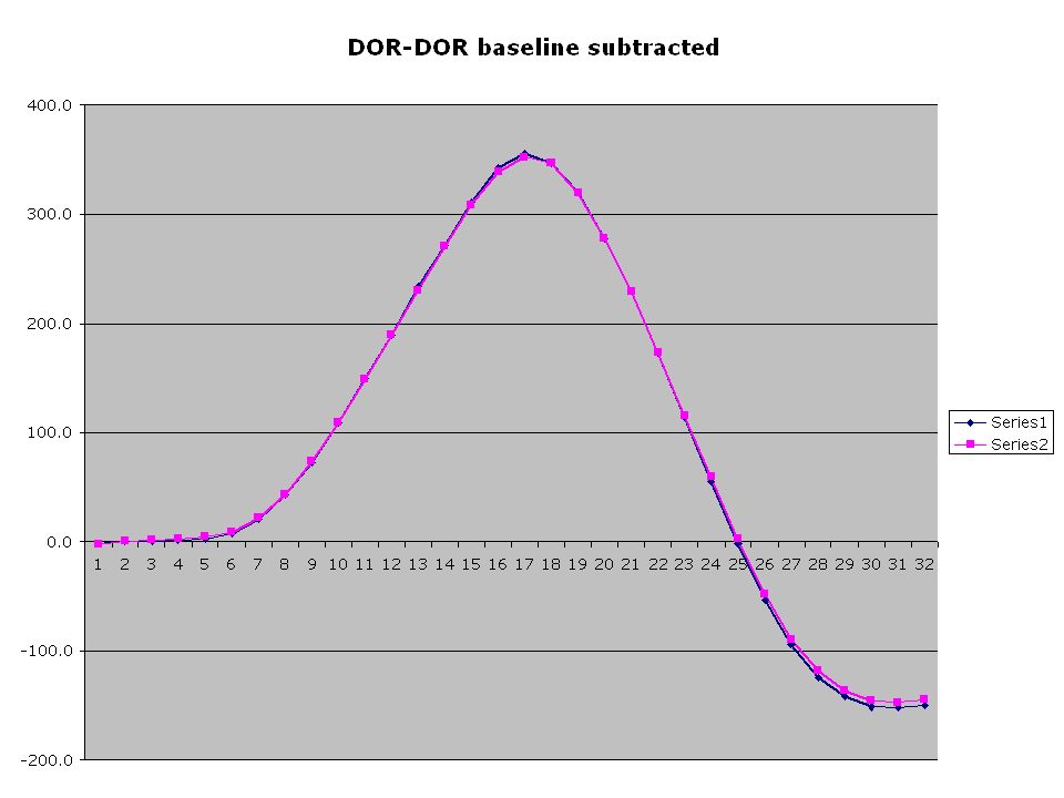
DOR-DOR shifted by one clock tick = 50 ns

27
VV t (ns) t av
 t av")
28
Average asymmetry = -1.3 ns RMS asymmetry = 1.1 ns DOR - DOR test DOR

29
DOR Card Av. Asymm RMS asymm DOM A -1.3 ns 1.1 ns DOM B -1.2 ns 1.1 ns DOR Card Test of Two DOM Configuration DOM A = 20 cm stub DOM B = 40 cm cable DOR DOM A DOM B Runs A_02_04N B_02_04N

30
Waveform Analysis Linear fit over limited range, calculate crossing point with pedestal Fit range

31
Round-Trip times using three methods Waveform template rms = 0.9 ns Linear fit rms = 3.9 ns Complicated fit rms = 7.2 ns Note: absolute scale on x-axis not adjusted properly. OK for residuals, however.

32
Using measured waveform as template and centroid of pulse appears promising. Simple, fast, accurate. Robust? (likely) Candidate for use in ice. Waveform Analysis Summary
 Candidate for use in ice. Waveform Analysis Summary.")
33
DOR - DOM typical results: Round trip time rms ~ 1 ns for 3.4 km cable in lab using template. (1ns in 37 s) Boards otherwise "quiet" No transmission of data in other twisted pair.
 Boards otherwise quiet No transmission of data in other twisted pair..")
34
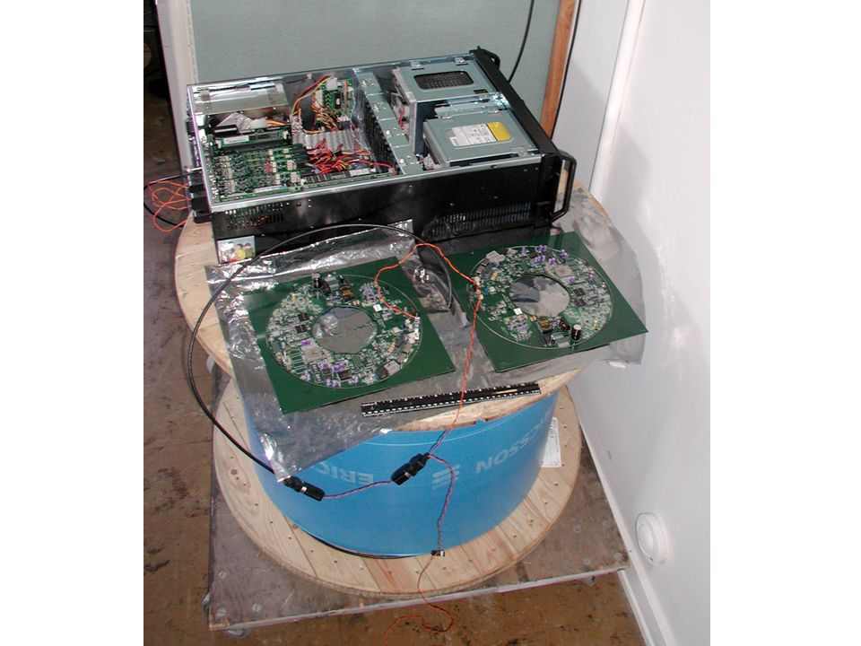
Cross-talk studies DOR - DOM 3.4 km Ericsson quad on spool Measure round trip rms deviation with and without data xmission at (1 Mbit/s) in other twisted pair
 in other twisted pair")
35
Cross-talk measurement results round trip residual (rms ns) DOM A DOM B Data transmission on 1.51.5 to another quad Data transmission on4.44.7 in Ericsson quad Runs X01_A,B X03_A,B => Most Cross-talk occurs in quad
 DOM A DOM B Data transmission on to another quad Data transmission on in Ericsson quad Runs X01_A,B X03_A,B => Most Cross-talk occurs in quad")
36
Timing error budget for clock calibration is 5 ns total - including frequency, offset, asymmetry. Conclude it is prudent to shut down data transmission during RAPCAL in order to meet timing requirement. Synchronized shutdown of communications for calibration is now the planned operating mode. Uses 0.5% bandwidth at 10 sec interval Uses 5% bandwidth at 1 sec interval (This option already envisioned in RapCal for IceCube.)
.")
37
Cable Stub Tests No Stub Configurations DOR DOMaDOMb 15 cm terminated unterminated 3.4 km cable end DOR DOMbDOMa 15 cm1750 cm3.4 km 12 DOR, DOMa, and DOMb are actually one DOR card

38
Cable Stub Tests Stub Configuration DOR DOMb DOMa 130 cm 1750 cm3.4 km 3

39
Stub test results (preliminary) DOMaDOMb asym rms 15-1549.90.749.70.5 15-175049.10.549.70.5 130-175049.70.449.80.7 (NB 1 clock tick = 50 ns. Above absolute asymmetry is due to systematic logic error and is < 1ns.) DOR card has single clock for all 3 channels => Can measure up - down asymmetry Use centroid of positive portion of pulse These results suggest that 1.3 m cable stub does not introduce an asymmetry with measurable effect on time calibration. 123123
 DOR card has single clock for all 3 channels => Can measure up - down asymmetry Use centroid of positive portion of pulse These results suggest that 1.3 m cable stub does not introduce an asymmetry with measurable effect on time calibration")
Similar presentations


 Brushless drives 1b) PC-104 Servo computer.>")