Download presentation
Presentation is loading. Please wait.

1
Copyright © SEL 2010 Advancements in Transmission Line Protection and Fault Location Brian Smyth Lead Product Engineer

2
Today’s Focus Need for better line protection Multiterminal 87L over Ethernet Using time in critical applications Traveling wave fault location Validating complex protection schemes

3
Line Protection Challenges Stressed power systems demand more from protection Transient stability margins Unusual system conditions 87L schemes address many problems

4
Multiterminal SEL-411L Over Ethernet

5
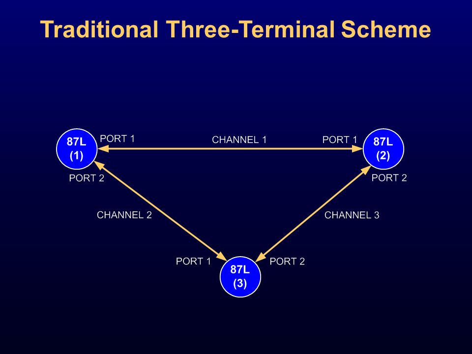
Multiterminal 87L Schemes Implementation Requirements Communication of current signals ♦ One-to-many data transmission ♦ Many-to-one data reception Current data alignment Algorithm suitable for multicurrent differential zones

6
Traditional Three-Terminal Scheme

8
Multiterminal Alpha Plane

9
Faults on 87L Alpha Plane 0 0 180 InternalExternal Multiterminal Alpha Plane I LQ EQ I RQ EQ I LQ EQ I RQ EQ

10
Four-Terminal Scheme

11
Four-Terminal Scheme Point-to-Point Serial? Impractical Number of ports and channels Data alignment challenges TerminalsPortsChannels 323 436 5410 6515

12
Four-Terminal Scheme Ethernet With Dedicated Fiber All relays receive all remote data Dedicated fiber between switches Isolated Layer 2 Ethernet network Optionally, a ring for fiber redundancy

13
SEL-411L Implementation Dedicated Ethertype from IEEE Layer 2 Ethernet VLAN for multiple 87L schemes Extra data integrity (Ethernet CRC) MAC addresses to identify relays in the same scheme
 MAC addresses to identify relays in the same scheme")
14
Four-Terminal Scheme Ethernet Over Protection-Class SONET All relays receive all data Relay to multiplexer over Ethernet TDM between multiplexers Advantages of SONET

15
87L Serial vs. Ethernet Over ICON Point-to-point between relay and multiplexer One physical connection per terminal ICON maps serial circuits between sites One point-to-point connection between relay and multiplexer ICON delivers packets based on VLAN

16
87L Algorithm for Multiterminal Applications Tried-and-true Alpha Plane Generalized Alpha Plane to handle any number of currents External fault detection for CT saturation Charging current compensation In-line transformers Technical paper “Tutorial on Operating Characteristics of Microprocessor-Based Multiterminal Line Current Differential Relays”

17
SEL-411L With 87L Over Ethernet Applicable with ♦ Isolated network with dedicated fiber ♦ Deterministic Ethernet over ICON Allows four-terminal applications Natural extension of serial applications Requires time for current alignment

18
Using Time in Critical Power System Applications

19
Time in Critical Applications Wide-area time needed for ♦ Line current differential ♦ Synchrophasors ♦ Multiended fault locators Need for robust time source and distribution Coherent time despite GPS problems

20
SONET Time Source and Distribution SONET keeps all multiplexers tightly synchronized ICON integrates GPS receivers GPS receivers act as redundant time inputs ICON provides coherent time across the network

21
Time Over ICON Simplicity Service ModuleLine Module GPS Antenna Input IRIG-B Outputs IRIG-B Input IEEE 1588 Timing Protocol (Future)
")
22
Advanced Time Synchronization SEL-2488 GPS Clock Need a good holdover state to be reliable TCXO = 36us/day OCXO = 5us/day

23
Traveling Wave Fault Location

24
Traveling Wave Fault Location Principle of Operation

25
Extracting the Waves 10 kHz to 0.6 MHz DC to 0.6 MHz

26
Traveling Wave Fault Locators (TWFLs) Accurate ♦ Down to a tower span ♦ Regardless of line length ♦ On series-compensated and coupled lines Immune to limitations of other methods ♦ Fault resistance and infeed effect ♦ Changing fault resistance ♦ Not enough data due to fast fault clearance
 Accurate ♦ Down to a tower span ♦ Regardless of line length ♦ On series-compensated and coupled lines Immune to limitations of other methods ♦ Fault resistance and infeed effect ♦ Changing fault resistance ♦ Not enough data due to fast fault clearance")
27
SEL Designed a TWFL Before... Dr. Schweitzer’s work in the mid-1980s for Bonneville Power Administration (dc lines)
.")
28
SEL-411L Implementation Current-based Double-ended, using arrival times 87L channel to exchange time stamps Built-in traveling wave oscillography In parallel with impedance-based fault locator

29
TWFL Feasibility in Protective Relays CT Primary CT Secondary CAL Board Output 10 s

30
SEL-411L TWFL Hardware 6 channels Sampling at 1.5625 MHz each

31
Traveling Wave Oscillography

32
Field Experience 72.78-mile 161 kV line at BPA (Goshen- Drummond) 18 sections with 4 different tower configurations
 18 sections with 4 different tower configurations")
33
Event on April 24, 2012 60 Hz View

34
Event on April 24, 2012 Traveling Wave View

35
Event on April 24, 2012 Front Wave

36
Event on April 24, 2012 Fault Location Results MethodMiles From Goshen Two-End Traveling Wave (SEL-411L)68.181 Two-End Impedance66.03 Single-End Impedance Relay 164.05 Single-End Impedance Relay 264.15 “Using this information we asked the line crew to go to 68.181 miles and they found the flashed insulator at 68.242 miles. This was within one tower off where we said to look. The first span from 68 mile is 551 feet, the second span is 725 feet. Picture of the April 24th flashover attached.” —Stephen Marx, BPA

37
Event on April 24, 2012 Flashed Over Insulator

38
Few More Examples Event Fault Location (Actual) Fault Location (SEL-411L) Flashover68.242 mi68.181 mi Insulator Damage38.398 mi38.426 mi Lightning StrikeUnder Investigation67.76 mi Lightning Strike Insulator Damage
 Fault Location (SEL-411L) Flashover mi mi Insulator Damage mi mi Lightning StrikeUnder Investigation67.76 mi Lightning Strike Insulator Damage")
39
Questions?

Similar presentations


 and point-to-point links, Ethernet,>")


 collecting field data connected back to a master station via a communications system.>")

 1 x E1/T1 over Ethernet Multiplexer (TDMoIP) Product.>")
