Download presentation
Presentation is loading. Please wait.

1
Chapter 7 Fatigue Failure Resulting from Variable Loading
Dr. A. Aziz Bazoune King Fahd University of Petroleum & Minerals Mechanical Engineering Department

2
Chapter Outline 7-1 Introduction to Fatigue in Metals Approach to Fatigue Failure in Analysis and Design Fatigue-Life Methods The Stress-Life Method The Strain-Life Method The Linear-Elastic Fracture Mechanics Method The Endurance Limit Fatigue Strength Endurance Limit Modifying Factors Stress Concentration and Notch Sensitivity Characterizing Fluctuating Stresses Fatigue Failure Criteria for Fluctuating Stress Torsional Fatigue Strength under Fluctuating Stresses Combinations of Loading Modes Varying, Fluctuating Stresses; Cumulative Fatigue Damage Surface Fatigue Strength Stochastic Analysis 373

3
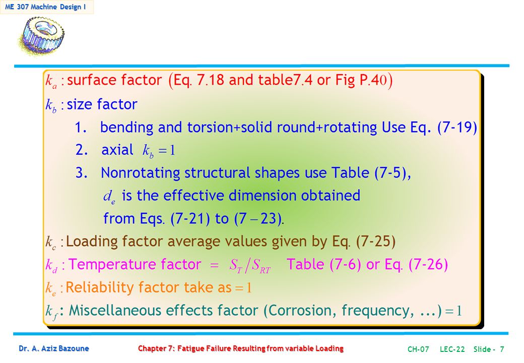
LECTURE-22 7-9 Endurance Limit Modifying Factors
7-10 Stress Concentration and Notch Sensitivity

4
7-9 Endurance Limit Modifying Factors
The rotating-beam specimen used in the laboratory to determine endurance limits is prepared very carefully and tested under closely controlled conditions. It is unrealistic to expect the endurance limit of a mechanical or structural member to match the values obtained in the laboratory. Some differences include Material: composition, basis of failure, variability Manufacturing: method, heat treatment, fretting corrosion, surface condition, stress concentration Environment: corrosion, temperature, stress state, relaxation times Design: size, shape, life, stress state, stress concentration, speed, fretting, galling

5
Marin’s Equation Marin identified factors that quantified the effects of surface condition size loading temperature miscellaneous items Marin’s Equations is therefore written as: (7-17)
")
6
Marin’s Equation rotary-beam test specimen endurance limit (7-17)
Endurance limit at the critical location of a machine part in geometry and condition of use rotary-beam test specimen endurance limit

8
(7-18) where is the minimum tensile strength and and are to be found in Table Notice that and are different from those given by Eqs. (7-13) and (7-14) respectively. Table 7-4 Parameters for Marin surface modification factor, Eq. (7-18)
 and (7-14) respectively. Table 7-4. Parameters for Marin surface modification. factor, Eq. (7-18)")
10
The size factor for bending and torsion may be given by:
(7-19) For axial loading there is no size effect, so (7-20)
 For axial loading there is no size effect, so. (7-20)")
11
Non-Rotating Parts If a round bar in bending is not rotating or when a non-circular cross-section is used what is kb ? Assume that fatigue damage occurs in material that is stressed above 95% of its maximum stress. Equate the portion of a non-round part stressed with the similarly stressed area of a rotating beam specimen and obtain the effective diameter where. (7-23) as the effective size of a round corresponding to a non-rotating solid or hollow round. Table 7-5 provides areas of common structural shapes undergoing non-rotating bending.
 as the effective size of a round corresponding to a non-rotating solid or hollow round. Table 7-5 provides areas of common structural shapes undergoing non-rotating bending.")
12
Table 7-5 Areas of common non-rotating structural shapes Use de Eq. (7-23) for round and Eq.(7-24) for rectangular cross-sections
 for round and Eq.(7-24) for rectangular cross-sections.")
13
General form of load factor
(7-25) Average kpsi MPa Bending 1 Axial 1.23 1.43 -0.078 0.85 Torsion 0.328 0.258 0.125 0.59 Values given in Textbook
 Average. kpsi. MPa. Bending. 1. Axial Torsion Values given in Textbook.")
14
(7-26) where
 where")
15
(7-27) Table 7-6 Effect of operating temperature on the tensile strength of steel.
 Table 7-6 Effect of operating temperature on the tensile strength of steel.")
16
If Reliability is not mentioned Otherwise Use Table 7-7
Table 7-7 Reliability factor Ka corresponding to 8% standard deviation of the endurance limit. If Reliability is not mentioned Otherwise Use Table 7-7

17
Residual stresses Directional characteristics (e.g. rolling, drawing) Corrosion Plating Metal spraying Frequency of cycling Fretting corrosion

18
7-10 Stress Concentration Factor and Notch Sensitivity
In Chapter 4, it was pointed out that: The existence of irregularities or discontinuities, such as holes, grooves or notches, in a part increases the theoretical stresses significantly in the immediate vicinity of discontinuity. (4-48)
")
19
7-10 Stress Concentration Factor and Notch Sensitivity

20
7-10 Stress Concentration Factor and Notch Sensitivity
In fatigue: Stress concentration should always be taken into account.

21
7-10 Stress Concentration Factor and Notch Sensitivity
Some materials are not fully sensitive to notches and a reduced value of Kt is used and the maximum stress is calculated as follows: (7-29) Kf is the fatigue stress concentration factor, for simple loading: (Ex 7.7) or
 Kf is the fatigue stress concentration factor, for simple loading: (Ex 7.7) or.")
22
Notch sensitivity q index is defined by
(7-39) q for steel and Al alloys are given in Fig for reversed bending or reversed axial load for reversed torsion use Fig For cast iron use q = 0.20 to be conservative.
 q for steel and Al alloys are given in Fig for reversed bending or reversed axial load for reversed torsion use Fig For cast iron use q = 0.20 to be conservative.")
23
Figure 7-20 and Figure 7-21: Notch sensitivity curves.

25
References Design Theory Resources Manufacturing

Similar presentations


 deformation of a material with time under a constant stress. It is both.>")


>")


