Download presentation
Presentation is loading. Please wait.

1
Diffraction Introduction to Diffraction Patterns
A plane wave of wavelength λ is incident on a barrier in which there is an opening of diameter d. (a) When λ<<d, the rays continue in a straight-line path, and the ray approximation remains valid. (b) When λ≈ d, the rays spread out after passing through the opening. (c) When λ>> d, the opening behaves as a point source emitting spherical waves.
 When λ<<d, the rays continue in a straight-line path, and the ray approximation remains valid. (b) When λ≈ d, the rays spread out after passing through the opening. (c) When λ>> d, the opening behaves as a point source emitting spherical waves.")
2
in Figure 24.13a, the waves wouldn’t overlap and no interference pattern would be seen.
In other words, the light bends from a straight line path and enters the region that would otherwise be shadowed. This spreading out of light from its initial line of travel is called diffraction. In general, diffraction occurs when waves pass through small openings, around obstacles, or by sharp edges. For example, when a single narrow slit is placed between a distant light source (or a laser beam) and a screen, the light produces a diffraction pattern like that in Figure
 and a screen, the light produces a diffraction pattern like that in Figure")
3
The pattern consists of a broad, intense central band flanked by a series of narrower, less intense secondary bands (called secondary maxima) and a series of dark bands, or minima. a)The Fraunhofer diffraction pattern of a single slit. The parallel rays are brought into focus on the screen with a converging lens. The pattern consists of a central bright region flanked by much weaker maxima. (This drawing is not to scale.) (b) A photograph of a single-slit Fraunhofer diffraction pattern. The bright spot at the centre (called the Fresnel bright spot ) is explained by Augustin Fresnel’s wave theory of , which predicts constructive interference at the centre of the shadow of a penne We can explain the central bright spot only by using the wave theory of light, which predicts constructive interference at this point. From the viewpoint of geometric optics
The Fraunhofer diffraction pattern of a single slit. The parallel rays are brought into focus on the screen with a converging lens. The pattern consists of a central bright region flanked by much weaker maxima. (This drawing is not to scale.) (b) A photograph of a single-slit Fraunhofer diffraction pattern. The bright spot at the centre (called the. Fresnel bright spot ) is explained by. Augustin Fresnel’s wave theory of , which predicts constructive interference. at the centre of the shadow of a penne. We can explain the central bright spot. only by using the wave theory of light, which predicts constructive interference at this point. From the viewpoint of geometric optics.")
4
Penny Shadow. From the viewpoint of geometric optics, there shouldn’t be any bright spot: the centre of the pattern would be completely screened by the penny. Figure 38.2 Light from a small source passes by the edge of an opaque object and continues on to a screen. A diffraction pattern consisting of bright and dark fringes appears on the screen in the region above the edge of the object.

5
One type of diffraction, called Fraunhofer diffraction, occurs when the rays leave the diffracting object in parallel directions. Fraunhofer diffraction can be achieved experimentally either by placing the observing screen far from the slit or by using a converging lens to focus the parallel rays on a nearby screen, as in Active Figure 24.16a. A bright fringe is observed along the axis at θ=0, with alternating dark and bright fringes on each side of the central bright fringe. Active Figure 24.16b is a photograph of a single-slit Fraunhofer diffraction pattern.

6
SINGLE-SLIT DIFFRACTION
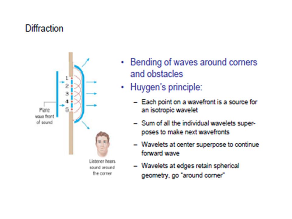
Until now we have assumed that slits have negligible width, acting as line sources of light. We can deduce some important features of this problem by examining waves coming from various portions of the slit, as shown in Figure According to Huygens’ principle, each portion of the slit acts as a source of waves. Hence, light from one portion of the slit can interfere with light from another portion, and the resultant intensity on the screen depends on the direction θ. it’s convenient to divide the slit into halves, as in Figure

7
All the waves that originate at the slit are in phase.
Consider waves 1 and 3, which originate at the bottom and centre of the slit, respectively. Wave 1 travels farther than wave 3 by an amount equal to the path difference (a/2) sin θ, where a is the width of the slit. Similarly, the path difference between waves 3 and 5 is(a/2) sin θ. If this path difference is exactly half of a wavelength (corresponding to a phase difference of 180°), the two waves cancel each other and destructive interference results. Therefore, waves from the upper half of the slit interfere destructively with waves from the lower half of the slit when or when
 sin θ, where a is the width of the slit. Similarly, the path difference between waves 3 and 5 is(a/2) sin θ. If this path difference is exactly half of a. wavelength (corresponding to a phase. difference of 180°), the two waves cancel. each other and destructive interference results. Therefore, waves from the upper half of the slit interfere destructively with waves from the lower half of the slit when. or when.")
8
If we divide the slit into four parts rather than two and use similar reasoning, we find that the screen is also dark when Continuing in this way, we can divide the slit into six parts and show that darkness occurs on the screen when Therefore, the general condition for destructive interference for a single slit of width a is

9
Equation gives the values of θ for which the diffraction pattern has zero intensity, where a dark fringe forms. the equation tells us nothing about the variation in intensity along the screen. The general features of the intensity distribution along the screen are shown in Figure

10
EXAMPLE Light of wavelength 5.80x 10² nm is incident on a slit of width mm. The observing screen is placed 2.00 m from the slit. Find the positions of the first dark fringes and the width of the central bright fringe. Solution The first dark fringes that flank the central bright fringe correspond to m =1 in Equation 24.11: Use the triangle in Figure to relate the position of the fringe to the tangent function: Because θ is very small, we can use the approximation sin θ ≈ tanθ and then solve for y1:

11
Compute the distance between the positive and negative first-order maxima, which is the width w of the central maximum:

12
SOLUTION: 632. 8nm/0. 12x1013 = 5. 27x10-3 =(12m)(5. 27x10-3m) =0
SOLUTION: 632.8nm/0.12x1013 = 5.27x10-3 =(12m)(5.27x10⁻³m) =0.063m w=2y=2x0.063=0.126m
(5.27x10⁻³m) =0.063m w=2y=2x0.063=0.126m")
14
Diffraction from a single slit of width D
interference between wavelets from different parts of the slit makes the “single slit” diffraction pattern… an interference pattern from a single slit!! Wavelet from top of slit destructive with wavelet from centre when

15
Every other point in slit can be paired with another in this way !
Diffraction pattern with minima at

18
THE DIFFRACTION GRATING
The diffraction grating, a useful device for analyzing light sources, consists of a large number of equally spaced parallel slits. A grating can be made by scratching parallel lines on a glass plate with a precision machining technique. The clear panes between scratches act like slits. A typical grating contains several thousand lines per centimetre. For example, a grating ruled with 5000 lines/cm has a slit spacing d equal to the reciprocal of that number; hence, d = (1/5 000) cm= 2 x 10⁻⁴ cm.
 cm= 2 x 10⁻⁴ cm.")
19
A plane wave is incident from the left, normal to the plane of the grating. The intensity of the pattern on the screen is the result of the combined effects of interference and diffraction. each slit acts as a source of waves, and all waves start in phase at the slits. For some arbitrary direction θ measured from the horizontal, however, the waves must travel different path lengths before reaching a particular point P on the screen.

20
From Figure 24.19, note that the path difference between waves from any two adjacent slits is d sin θ. If this path difference equals one wavelength or some integral multiple of a wavelength, waves from all slits will be in phase at P and a bright line will be observed at that point. Therefore, the condition for maxima in the interference pattern at the angle θ is or

21
Light emerging from a slit at an angle other than that for a maximum interferes nearly completely destructively with light from some other slit on the grating. All such pairs will result in little or no transmission in that direction, as illustrated in Active Figure

22
Equation can be used to calculate the wavelength from the grating spacing and the angle of deviation, θ. The integer m is the order number of the diffraction pattern. Figure is a sketch of the intensity distribution for some of the orders produced by a diffraction grating.

24
All wavelengths are focused at θ= 0, corresponding to m = 0
All wavelengths are focused at θ= 0, corresponding to m = 0. This is called the zeroth-order maximum. The first-order maximum, corresponding to m= 1, is observed at an angle that satisfies the relationship sin θ = λ/d; the second-order maximum, corresponding to m = 2, is sin θ2 = ±2λ/d observed at a larger angle θ, and so on. For m=3, sin θ3 = ±3λ/d

25
EXAMPLE Monochromatic light from a helium–neon laser (λ=632.8 nm) is incident normally on a diffraction grating containing 6.00 x 10³ lines/cm. Find the angles at which one would observe the first-order maximum, the second-order maximum, and so forth. Solution Invert the number of lines per centimetre to obtain the slit separation:
 is incident normally on a diffraction grating containing 6.00 x 10³ lines/cm. Find the angles at which one would observe the first-order maximum, the second-order maximum, and so forth. Solution. Invert the number of lines per centimetre to obtain the slit separation:")
26
Substitute m = 1 into Equation 24
Substitute m = 1 into Equation to find the sine of the angle corresponding to the first-order maximum: Take the inverse sine of the preceding result to find θ1: Repeat the calculation for m = 2: Repeat the calculation for m = 3:

Similar presentations


Light bends around corners. ii)“Shadows” fill in iii)“Parallel” beams always spread iv)Limits of resolution.>")

 Light and.>")


.>")
 believed that light consisted of particles or corpuscles. The Dutch scientist, Christian Huygens (1629-1695), agreed.>")

 optics. Sometimes called.>")

