Download presentation
Presentation is loading. Please wait.

1
UCN Facility Working Group October 3, 2012 OverviewL.Lee MCNPX and ShieldingP.Carlson Beam MonitorsC.A.Davis / A.Konaka

2
UCN Facility Working Group October 3, 2012 OverviewL.Lee - Schedule & 2014 Shutdown - Decisions about beamline configurations - High-density shielding (Vault-1A “Plug”, UCN Pyramid) - Shielding needs (Monte Carlo studies) MCNPX and ShieldingP.Carlson Beam MonitorsC.A.Davis / A.Konaka
 - Shielding needs (Monte Carlo studies) MCNPX and ShieldingP.Carlson Beam MonitorsC.A.Davis / A.Konaka")
3
2011 2015 2014 2013 2012 2016 2017 ACTIVITY J A J O J A Schedule( 2010-2016 ) 2011 2015 2014 2013 2012 2016 2017 Cleanup M11,1A/1B roof-beam Dismantle PIENU & M13-DS MESON HALL (& Vault): Core M13 I-block Shielding UCN APPARATUS: Spallation Target & R/H UCN Source BEAMLINE 1U: Kicker Septum Dipole Beamline (incl Quads, PS,…) Design & ReviewOrder/Fabricate/Deliver Test Order/Mod Order/Fabricate Design & Review Order/Fabricate InstallTest Specify/Conceptual design Design/FabricateInstallUnInstall Procure shielding blocksDesign & Review Install COMMISSION @ TRIUMF Beamline Commissioning HELIUM LIQUEFIER: Upgrade He Liquefier System He Liquefier System Procure UCN Source Commissioning Install/Test & Run @ RCNP Procure/Install Install Kicker Ceramic Beamtube Install Design/OrderFabricate Install Test MILESTONES Shutdown Activities Activities Elsewhere (KEK, RCNP, CERN, Acsion) Non-Shutdown Activities Mod. 1VQ4/Q5; BL1V & Shld Install Dismantle M13-US, Mod.Shld UCN Schedule (Draft) Design/Order/FabricateTest Install Design/Fab r
 Design/Order/FabricateTest Install Design/Fab r.")
4
N Kick direction (vertical or horizontal) Shielding “Plug” will need to be reconfigured UCN Installation 2014
 Shielding Plug will need to be reconfigured UCN Installation 2014")
5
Decisions about beamline configurations

6
Transporting the split beam from the kicker through the existing beam apertures

9
UCN Installation 2015 (Option 3f) N T1 study
 N T1 study")
10
UCN Installation 2015 (Option 3g) N T1 study
 N T1 study")
11
High-density Shielding

12
Shielding Plug Layout: Option-1 Replace some concrete with steel blocks ( ~ 3:1 thickness ratio) “First-Pass” study using SolidWorks 3D-Model of Meson Hall West
 First-Pass study using SolidWorks 3D-Model of Meson Hall West")
13
Higher Density Shielding Materials Replacing some concrete blocks with higher density material Issues/Considerations: - Re-use existing concrete blocks, as much as possible Costs, Storage fewer removed blocks (potentially activated) - Combine with denser (Steel) blocks - Combine with denser (Hematite-aggregate concrete) blocks Concrete/Hematite aggregate shielding blocks (from NSS) Variable/Customizable density (3.8 - 5.7 g/cc) Used at reactors (Ontario – 25 yrs), SNS, TRIUMF NSS has worked with Ellis-Don, Burnco, LaFarge NSS Meeting at TRIUMF on Sep.10, 2012 (M.Chopra) Layout Options (“First-Pass” study): (1) Replace some concrete w/ steel blocks ( ~ 3:1 thickness ratio) (2) Replace some concrete w/ aggregate blocks ( ~ 2:1 thickness ratio)
 - Combine with denser (Steel) blocks - Combine with denser (Hematite-aggregate concrete) blocks Concrete/Hematite aggregate shielding blocks (from NSS) Variable/Customizable density ( g/cc) Used at reactors (Ontario – 25 yrs), SNS, TRIUMF NSS has worked with Ellis-Don, Burnco, LaFarge NSS Meeting at TRIUMF on Sep.10, 2012 (M.Chopra) Layout Options ( First-Pass study): (1) Replace some concrete w/ steel blocks ( ~ 3:1 thickness ratio) (2) Replace some concrete w/ aggregate blocks ( ~ 2:1 thickness ratio)")
14
SolidWorks 3D-Model of Meson Hall West CYCL. VAULT BL1A TUNNEL

15
Beampipe to BL1A Immovable Block East (to T1, T2, TNF) Existing Shielding (Layers A-D) (UPPER LAYERS E-J HIDDEN) Vault-1A “Plug”
 Existing Shielding (Layers A-D) (UPPER LAYERS E-J HIDDEN) Vault-1A Plug")
16
List of “Removed” Concrete Blocks:List of “New” Blocks: (2) 12’ x 6’ x 4’(Layer A, C)(5) 2’ x 3’ x 6’ steel (Layer A) (7) 2’ x 3’ x 6’(Layer A)(1) 2’ x 3’ x 6’ steel*(Layer A) (1) 6’ x 3’ x 2’(Layer C)(2) 2’ x 3’ x 6’ concrete* (Layer A) (5) 2’ x 3’ x 2’(Layer D)(1) 6’ x 3’ x 2’ concrete* (Layer C) (6) 2’ x 3’ x 2’ steel (Layer D) (38% of existing) *block with “cut-out” for 1U beampipe Vault-1A Shielding Layout (Layers A-D) EXISTING vs “NEW” (OPTION-1, STEEL)
 12’ x 6’ x 4’(Layer A, C)(5) 2’ x 3’ x 6’ steel (Layer A) (7) 2’ x 3’ x 6’(Layer A)(1) 2’ x 3’ x 6’ steel*(Layer A) (1) 6’ x 3’ x 2’(Layer C)(2) 2’ x 3’ x 6’ concrete* (Layer A) (5) 2’ x 3’ x 2’(Layer D)(1) 6’ x 3’ x 2’ concrete* (Layer C) (6) 2’ x 3’ x 2’ steel (Layer D) (38% of existing) *block with cut-out for 1U beampipe Vault-1A Shielding Layout (Layers A-D) EXISTING vs NEW (OPTION-1, STEEL)")
17
List of “Removed” Concrete Blocks:List of “New” Blocks: (2) 12’ x 6’ x 4’(Layer A, C)(7) 2’ x 3’ x 6’ aggregate (Layer A) (6) 2’ x 3’ x 6’(Layer A)(1) 2’ x 3’ x 6’ aggregate*(Layer A) (5) 6’ x 3’ x 2’(Layer A, B, C)(2) 2’ x 3’ x 6’ concrete* (Layer A) (4) 2’ x 3’ x 2’(Layer D)(1) 6’ x 3’ x 2’ concrete* (Layer C) (8) 2’ x 3’ x 2’ aggregate (Layer D) (42% of existing) *block with “cut-out” for 1U beampipe Vault-1A Shielding Layout (Layers A-D) EXISTING vs “NEW” (OPTION-2, AGGREGATE)
 12’ x 6’ x 4’(Layer A, C)(7) 2’ x 3’ x 6’ aggregate (Layer A) (6) 2’ x 3’ x 6’(Layer A)(1) 2’ x 3’ x 6’ aggregate*(Layer A) (5) 6’ x 3’ x 2’(Layer A, B, C)(2) 2’ x 3’ x 6’ concrete* (Layer A) (4) 2’ x 3’ x 2’(Layer D)(1) 6’ x 3’ x 2’ concrete* (Layer C) (8) 2’ x 3’ x 2’ aggregate (Layer D) (42% of existing) *block with cut-out for 1U beampipe Vault-1A Shielding Layout (Layers A-D) EXISTING vs NEW (OPTION-2, AGGREGATE)")
18
High Density Concrete w/ Aggregate Nuclear Shielding Supplies and Services (NSS) Concrete/Hematite aggregate shielding blocks – HD (3.8-5.7 g/cc) - Hematite (Fe 2 O 3 ): Coarse [1” 3/8”] & Fine [3/8” 100 mesh] components Established history of use at reactors and accelerators - Ontario Hydro (20 yrs, P.Mukherjee: Study of long-term effect on HD concrete at reactors) - BNL AGS (ilmenite, roof beams: 33 ton, blocks: 21, 11, 0.5 – 2 ton) - SNS Tunnel (hematite, 3.85g/cc, poured in place, 2000 m 3 ) - TRIUMF NSS has worked with Ellis-Don, Burnco, LaFarge Used in both radiation & non-radiation applications: - high density radiation shielding - linear accelerator vaults & treatment rooms - high dose rate HDR rooms - mass concrete projects - high density concrete applications columns - gravity seawall, coastal protection & breakwater structures - bridge counterweights - ballast for ocean vessels and off shore platforms - noise and vibration dampening Coarse Hematite Fine Hematite
![High Density Concrete w/ Aggregate Nuclear Shielding Supplies and Services (NSS) Concrete/Hematite aggregate shielding blocks – HD ( g/cc) - Hematite (Fe 2 O 3 ): Coarse [1 3/8 ] & Fine [3/8 100 mesh] components Established history of use at reactors and accelerators - Ontario Hydro (20 yrs, P.Mukherjee: Study of long-term effect on HD concrete at reactors) - BNL AGS (ilmenite, roof beams: 33 ton, blocks: 21, 11, 0.5 – 2 ton) - SNS Tunnel (hematite, 3.85g/cc, poured in place, 2000 m 3 ) - TRIUMF NSS has worked with Ellis-Don, Burnco, LaFarge Used in both radiation & non-radiation applications: - high density radiation shielding - linear accelerator vaults & treatment rooms - high dose rate HDR rooms - mass concrete projects - high density concrete applications columns - gravity seawall, coastal protection & breakwater structures - bridge counterweights - ballast for ocean vessels and off shore platforms - noise and vibration dampening Coarse Hematite Fine Hematite](http://images.slideplayer.com/26/8457474/slides/slide_18.jpg "High Density Concrete w/ Aggregate Nuclear Shielding Supplies and Services (NSS) Concrete/Hematite aggregate shielding blocks – HD ( g/cc) - Hematite (Fe 2 O 3 ): Coarse [1 3/8 ] & Fine [3/8 100 mesh] components Established history of use at reactors and accelerators - Ontario Hydro (20 yrs, P.Mukherjee: Study of long-term effect on HD concrete at reactors) - BNL AGS (ilmenite, roof beams: 33 ton, blocks: 21, 11, 0.5 – 2 ton) - SNS Tunnel (hematite, 3.85g/cc, poured in place, 2000 m 3 ) - TRIUMF NSS has worked with Ellis-Don, Burnco, LaFarge Used in both radiation & non-radiation applications: - high density radiation shielding - linear accelerator vaults & treatment rooms - high dose rate HDR rooms - mass concrete projects - high density concrete applications columns - gravity seawall, coastal protection & breakwater structures - bridge counterweights - ballast for ocean vessels and off shore platforms - noise and vibration dampening Coarse Hematite Fine Hematite")
19
Charles River Suspension Bridge in Boston, MA NSS HD-concrete (Non-radiation Applications) HD-concrete Back-spans
 HD-concrete Back-spans")
20
Breakwater Structure Utilizing High Density Concrete NSS HD-concrete (Non-radiation Applications)
")
21
UCN Installation 2015/2016 (Option 3f) N High-density Non-magnetic Shielding Dose Limit: 3 Sv/h outside of shielding
 N High-density Non-magnetic Shielding Dose Limit: 3 Sv/h outside of shielding")
22
EXTRA

23
UCN Installation Schedule N 2014 Shutdown 2015 Shutdown 2015 Non-Shutdown & 2016 Shutdown

24
Optics Studies

25
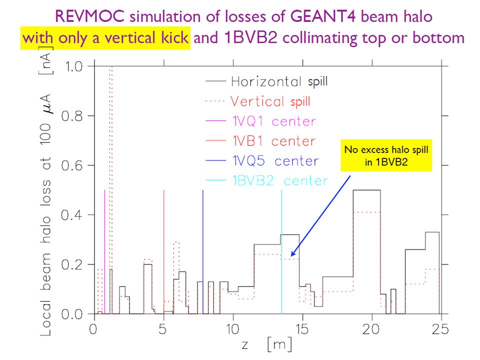
Vault-BL1A/1U Shielding Requirements What are the requirements for the shielding “plug” with BL1U installed? (Preliminary discussions with A.Trudel) - Prompt Radiation Hazard (PRH) Study - Based on occupancy in 1A/1U tunnel with beam ON in vault: Dose rate in accessible areas < 100 Sv/hr Annual personnel dose limits from chronic losses < 1 mSv - Dose rate constraints for various accidental full beam loss scenarios (e.g. accidental insertion of 1A stripper, failure of 2AVB1 bender) Dose rate outside shielding < 50 mSv/hr Dose limit per full loss event < 1 mSv How thick does the “new” shielding need to be? - Based on dose rates from various scenarios mentioned above (PRH study, simulation studies, surveys/measurements) - Design to maintain overall effective thickness ( t ) in shielding “plug” Is a Shielding-Plug “Task Force” needed? Layout Option: Maintain effective thickness of shielding Replace some of the concrete w/ higher density mat’l
 - Prompt Radiation Hazard (PRH) Study - Based on occupancy in 1A/1U tunnel with beam ON in vault: Dose rate in accessible areas < 100 Sv/hr Annual personnel dose limits from chronic losses < 1 mSv - Dose rate constraints for various accidental full beam loss scenarios (e.g. accidental insertion of 1A stripper, failure of 2AVB1 bender) Dose rate outside shielding < 50 mSv/hr Dose limit per full loss event < 1 mSv How thick does the new shielding need to be. - Based on dose rates from various scenarios mentioned above (PRH study, simulation studies, surveys/measurements) - Design to maintain overall effective thickness ( t ) in shielding plug Is a Shielding-Plug Task Force needed. Layout Option: Maintain effective thickness of shielding Replace some of the concrete w/ higher density mat’l.")
26
Vault Elements

27
Existing Shielding (Layer A) (LAYERS B+C+D & UPPER LAYERS E-J HIDDEN)
 (LAYERS B+C+D & UPPER LAYERS E-J HIDDEN)")
28
“New” Shielding Layout (Layer A) “FIRST-PASS” STUDY : OPTION-1 (STEEL) Blue – steel, new Yellow – concrete, new (w/ cut-out)
 FIRST-PASS STUDY : OPTION-1 (STEEL) Blue – steel, new Yellow – concrete, new (w/ cut-out)")
29
“New” Shielding Layout (Layer A+B) “FIRST-PASS” STUDY : OPTION-1 (STEEL) Blue – steel, new Yellow – concrete, new (w/ cut-out)
 FIRST-PASS STUDY : OPTION-1 (STEEL) Blue – steel, new Yellow – concrete, new (w/ cut-out)")
30
“New” Shielding Layout (Layer A+B+C) “FIRST-PASS” STUDY : OPTION-1 (STEEL) Blue – steel, new Yellow – concrete, new (w/ cut-out)
 FIRST-PASS STUDY : OPTION-1 (STEEL) Blue – steel, new Yellow – concrete, new (w/ cut-out)")
31
“New” Shielding Layout (Layer A+B+C+D) “FIRST-PASS” STUDY : OPTION-1 (STEEL) Blue – steel, new Yellow – concrete, new (w/ cut-out)
 FIRST-PASS STUDY : OPTION-1 (STEEL) Blue – steel, new Yellow – concrete, new (w/ cut-out)")
Similar presentations
 L.Lee.>")

 Muon Dose Rate > 1 mRem/hr for 0.1% Collimated Halo.>")


 14 March ‘02 NuMI / MINOS Overview.>")
 UCN Timeline & Major Milestones 2011 2015 2014 2013 2012 2016 2017 Remove.>")


>")

 Linac Booster Main Injector Startup.>")

>")


 L.Lee.>")