Download presentation
Presentation is loading. Please wait.

1
G1 Supplemental Questions

2
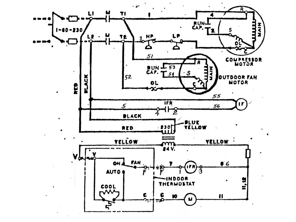
Question 1 What type of single phase motors are used for the compressor, outdoor fan motor and indoor fan motor? Move onto the next slide to determine your answer.

4
Indoor fan motor – Shaded Pole
What’s your answer? Compressor motor – PSC Outdoor fan motor – PSC Indoor fan motor – Shaded Pole

5
Question 2 Does the compressor have an overload, and if so, is it internal or external? Move onto the next slide to determine your answer.

7
What’s your answer? Internal

8
Question 3 Whose identification code is used with the thermostat? Move onto the next slide to determine your answer.

10
What’s your answer? ITT This is a very old schematic since ITT’s ID code has not been used for many years now.

11
Question 4 The contactor for the compressor and outdoor fan motor is identified with __________ letter. Move onto the next slide to determine your answer.

13
What’s your answer? M

14
Question 5 What is the purpose of the blue/yellow wire tap on the transformer primary? Move onto the next slide to determine your answer.

16
What’s your answer? The tap is so that this transformer can be used on either 208 or 230 volts. Red to Yellow/Blue is for 208v and Red to Black is for 230v. This supply voltage for this equipment is 230v, so noted, therefore the schematic shows L1 and L2 connected to Red and Black. Check it out.

17
Question 6 What is the rectangle in the ‘yellow’ wire of the low voltage circuit, and which wire is it found in? Move onto the next slide to determine your answer.

19
What’s your answer? The rectangle is a ‘fuse.’ A rectangle can be used as a symbol for a fuse. The wire that the fuse is found in is the ‘common’ wire of the transformer. Many times when a fuse is used on the low voltage circuit, it is found on the ‘return’ or ‘common’ side of the circuit.

20
Question 7 Notice the IFR in the low voltage circuit. It has a number 1 to the left and a number 3 to the right of the coil. What do these numbers represent? Move onto the next slide to determine your answer.

22
What’s your answer? Since the numbers are right where the ‘dots’ are, they indicate wire connection points. The numbers represent the ID code on the relay for the coil.

23
Question 8 To the left of the IFR coil there are numbers 7 and What do these numbers represent? Move onto the next slide to determine your answer.

25
What’s your answer? Since the numbers are NOT where the ‘dots’ are, they indicate actual wires. The numbers represent the ID code on the wire. We don’t usually see this on schematics. This is done at the factory. The folks on the production line use this type of diagram to wire the equipment.

26
Question 9 Likewise, to the left of the ‘M’ coil there are numbers. What do these numbers represent? Move onto the next slide to determine your answer.

28
What’s your answer? Since the numbers are NOT where the ‘dots’ are, they indicate actual wires. The numbers represent the ID code on the wire. We don’t usually see this on schematics. This is done at the factory. The folks on the production line use this type of diagram to wire the equipment.

29
Question 10 What is the switching action of the IFR? Move onto the next slide to determine your answer.

31
I hope you answered SPST –NO.
What’s your answer? I hope you answered SPST –NO.

32
Question 11 What is the switching action of the ‘M’ contactor? Move onto the next slide to determine your answer.

34
I hope you answered DPST.
What’s your answer? I hope you answered DPST.

35
Question 12 What is the source voltage, frequency and phase? Move onto the next slide to determine your answer.

37
You should have answered: 120v, 60Hz, 1 Phase
What’s your answer? You should have answered: 120v, 60Hz, 1 Phase

38
Question 13 What do the ‘M’ letter designations L1, L2, T1 and T2 represent? Move onto the next slide to determine your answer.

40
What’s your answer? L1 and L2 represent the power coming in (source) connections. T1 and T2 represent the power going out to the ‘load.’

41
THE END

Similar presentations


/40GXC(Q) Service Training Sizes 18 and 24K.>")


