Download presentation
Presentation is loading. Please wait.

1
Lec 4 . Graphical System Representations and Simplifications
Block Diagrams Signal Flow Graphs and Mason’s Formula Reading: TexPoint fonts used in EMF. Read the TexPoint manual before you delete this box.: AAAA

2
Block Diagrams Graphical representation of interconnected systems
A system may consist of multiple subsystems: the output of one may be the input to another Each subsystem is represented by a functional block, labeled with the corresponding transfer function Blocks are connected by arrows to indicate signal flow directions Advantage Easy for visualization purpose Can represent a class of similar systems

3
Basic Components of Block Diagrams
Signal flow (Functional) block Summing point + Branch point
 block. Summing point. + Branch point.")
4
Cascaded/Parallel Connected Systems
Cascaded systems: Parallel connected systems: +

5
(Negative) Feedback Connected Systems
+ Feedforward transfer function (FTF): Open-loop transfer function (OTF): Closed-loop transfer function (CTF):
: Open-loop transfer function (OTF): Closed-loop transfer function (CTF):")
6
Positive Feedback Connected Systems
+ Closed-loop transfer function: Remark: can be thought of as negative feedback connected system with feedback element –H(s)
")
7
Unity Feedback System Unit feedback connected systems: H(s)=1
+ Closed-loop transfer function:

8
Feedback Control System
controller plant + Closed-loop transfer function: Remark: by adjusting the controller C(s), one can change the close-loop transfer function to achieve desired properties.
, one can change the close-loop transfer function to achieve desired properties.")
9
Block Diagram Reduction
Often times the block diagram under study is complicated Use previous basic steps to reduce the complexity of block diagram Example: + +

10
Another Example + +

11
Operations for Simplifying Block Diagrams
“Slide a branch point past a functional block (forward)”
")
12
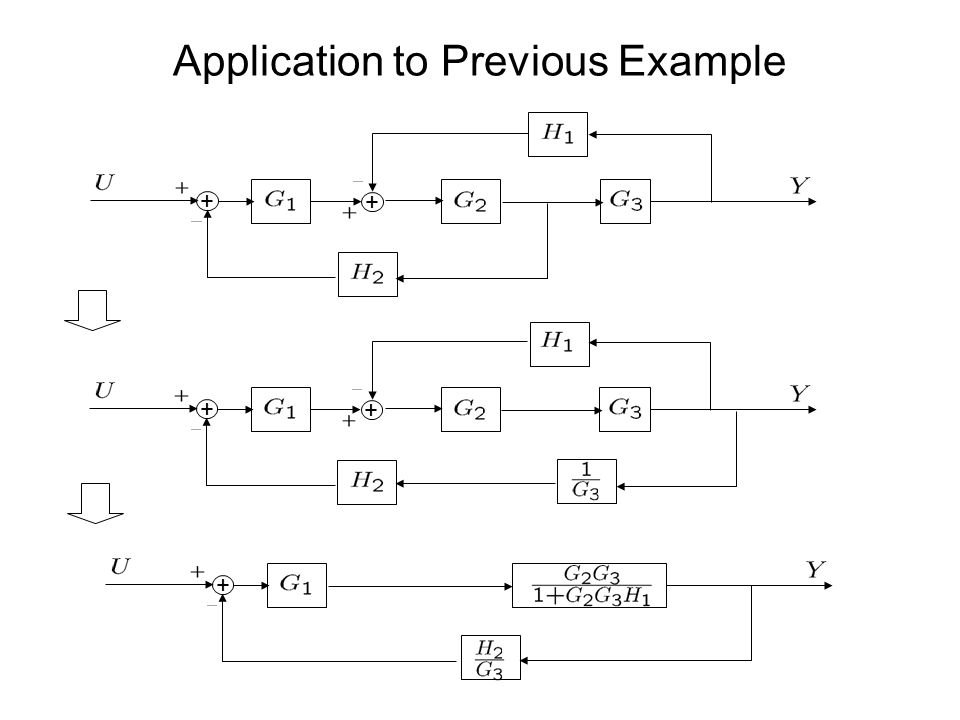
Application to Previous Example
+ +

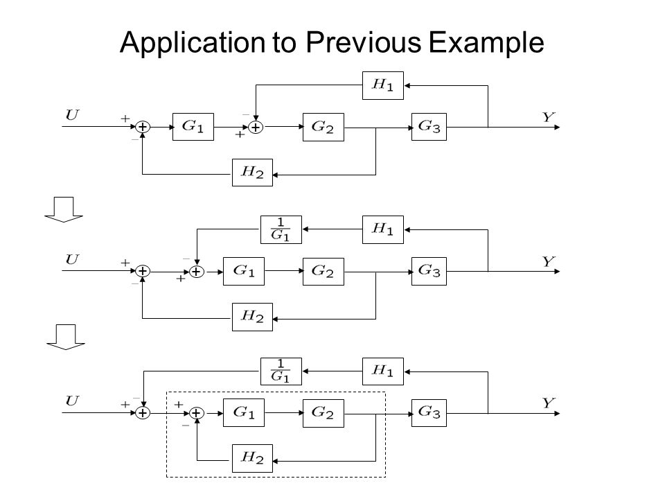
13
Application to Previous Example
+ + + + +
14
Another Operation for Simplifying Block Diagrams
“Slide a summation point past a functional block (backward)” + +
 + +")
15
Application to Previous Example
+ +

16
Application to Previous Example
+ + + + + +
17
Yet Another Simplifying Operation
“Slide a summation point past a functional block (forward)” + + Compare with: “Slide a branch point past a functional block (forward)”
 + + Compare with: Slide a branch point past a functional block (forward)")
18
Signal Flow Graphs An alternative graphical representation of interconnections of subsystems Advantage compared with block diagrams A systematic way to compute the transfer function from any input to any output

19
A Simple Example Block diagram: Signal flow graph:
+ Basic component of a signal flow graph: Node: represents a signal Each node is labeled with the corresponding signal Branch: directed line segment connecting two nodes Signal can only flow along the specified direction Each branch is associated with a transmittance or gain

20
Type of Nodes Input nodes: nodes with only outgoing branches
Block diagram: Signal flow graph: + Input nodes: nodes with only outgoing branches Output nodes: nodes with only incoming branches Mixed nodes: both incoming and outgoing branches An output node can be made from an arbitrary node by adding an outgoing branch of unit gain

21
What Happen At a Mixed Node?
At a mixed node, signals of all incoming branches are added and the result is transmitted to all outgoing branches At node Z: At node U: At node W: At node W:

22
A More Complicated Example
Block diagram: + + Signal flow graph:

23
Simplifying Signal Flow Graphs
Cascaded systems: Parallel connected systems: Feedback connected systems:

24
However, In General Transfer function from U to Y?

25
Mason’s Formula: A Direct Approach
Path: a sequence of connected branches (following arrow directions) Forward path: start from an input node and end at an output node Forward path gain: product of all branch gains along a forward path Loop: a closed path (starts and ends at the same node) Loop gain: product of all branch gains along a loop Notouching loops: loops that do not have shared nodes
 Forward path: start from an input node and end at an output node. Forward path gain: product of all branch gains along a forward path. Loop: a closed path (starts and ends at the same node) Loop gain: product of all branch gains along a loop. Notouching loops: loops that do not have shared nodes.")
26
Determinant of A Graph =1- (sum of all individual loop gains)
+ (sum of gain products of all two nontouching loops) - (sum of gain products of all three nontouching loops) + … Determinant of a graph without any loop is 1 Example:
 - (sum of gain products of all three nontouching loops) + … Determinant of a graph without any loop is 1. Example:")
27
Mason’s Formula Transfer function from an input node to an output node
Compute the determinant of the signal flow graph Find all forward paths with path gains P1,…,Pk For each forward path Pi, find its cofactor i , i.e., the determinant of the sub-graph with all the loops touching Pi removed Transfer function from input node to the output node is given by

28
Application to the Previous Example
Forward path Forward path gain Pi i

29
Another Example

30
Systems with Multiple Inputs and Outputs
MIMO system m inputs u1,…,um n outputs y1,…,yn Laplace transform of the k-th output is where is the transfer function from ui to yk Transfer matrix:

31
Example I One input: F Two outputs: x and y
Transfer matrix H(s)=[H1(s), H2(s)]
=[H1(s), H2(s)]")
32
Example II Two inputs: u1, u2 Two outputs: y1, y2
Transfer matrix H(s)? + +
 + +")
Similar presentations


 Why SFG? Block Diagrams are adequate for representation, but cumbersome. SFG provides the relation between system.>")


 + - R(s) Y(s) E(s)>")
>")