Download presentation
Presentation is loading. Please wait.

1
EXAMPLE 9.3 – Part V PCI Bridge Design Manual BULB “T” (BT-72) THREE SPANS, COMPOSITE DECK LRFD SPECIFICATIONS Materials copyrighted by Precast/Prestressed Concrete Institute, 2011. All rights reserved. Unauthorized duplication of the material or presentation prohibited.

2
SHEAR DESIGN Starting with LRFD V1, concrete changed to the “sectional model” a.k.a. compression field theory. The sectional model went through several iterations. With V 4, LRFD restored the shear models used in the old Standard Specification, with some modification, as alternate design methods.

3
SHEAR DESIGN This example will demonstrate both the sectional design model and the alternate design model. Due to time constraints, only the middle span beam will be designed and only one sample calculation will be shown for each method. Graphs will be presented to show the results for the entire beam.

4
SHEAR DESIGN – COMMON ELEMENTS For both methods, the beam is divided into sections. Usually: –The critical section for shear –Every 0.1L –Certain other critical points (like harp points) V u < (V c + V s ) V s is calculated the same way for both methods. Both methods use the shear depth, d v, defined as the distance between the compressive and tensile resultant.
 V u < (V c + V s ) V s is calculated the same way for both methods. Both methods use the shear depth, d v, defined as the distance between the compressive and tensile resultant..")
5
Definition of d v for a rectangular section. d v = d – a/2 d is the depth to the centroid of all tensile steel. SHEAR DESIGN – COMMON ELEMENTS

6
SECTIONAL MODEL (5.8.3) The sectional model is based on compression field theory. It models the beam as an internal truss. The uncracked block is the compression chord, the steel is the tensile chord and the stirrups are the vertical members. The diagonals are compression struts in the concrete.

7
SECTIONAL MODEL (5.8.3) A FBD can be drawn: Basically, the model assumes that the stirrups yield and stretch. Once this happens, the compression strut fails. Thus, the strength is the strength of the concrete strut + the strength of the stirrups + vertical component of the prestressing: V c + V s + V p.

8
SECTIONAL MODEL (5.8.3) The sectional model requires two factors: = the angle of the strut. = a factor which describes the strength of the strut. and can be found from equations or from tables in Appendix B, Chapter 5.

9
SECTIONAL MODEL (5.8.3) Where the reaction force in the direction of the applied shear introduces compression into the end region of a member, the location of the critical section for shear shall be taken as d v from the internal face of the support; otherwise use the face of the support.
 Where the reaction force in the direction of the applied shear introduces compression into the end region of a member, the location of the critical section for shear shall be taken as d v from the internal face of the support; otherwise use the face of the support.")
10
The critical section occurs in the negative moment zone. From previous calculations: SECTIONAL MODEL (5.8.3)
.")
11
The critical section is taken from the face of the support. In this example, it is conservatively taken as d v =73.25 inches from the center of bearing. Find V u and M u at the critical section. Note that the critical section occurs in the negative moment zone. However, the beam has some positive moments from the simple span loads (self weight and deck weight). Therefore, we must account for cases where the moments act opposite to each other by using maximum and minimum load factors. SECTIONAL MODEL (5.8.3)
. Therefore, we must account for cases where the moments act opposite to each other by using maximum and minimum load factors. SECTIONAL MODEL (5.8.3).")
12
The critical section is 6.1 ft from center of bearing. In this table, center of bearing is 1 ft from end, so the critical section is at 7.1 feet in this table. SECTIONAL MODEL (5.8.3)
.")
13
Using the values of shear and moment calculated in the table in the Bridge Manual: M u = 1.25(273+417-140)+1.5(-244)+1.75(-1718) = -2685 k-ft V u = 1.25(42+65+7.8)+1.5(14.2)+1.75(137) = 405 k CONTROLS M u = 0.9(273+417-140)+1.5(-244)+1.75(-1718) = -2878 k-ft CONTROLS V u = goes the same way, so N/A. The code allows taking the largest value of V u and M u, even if they don’t occur for the same load case. SECTIONAL MODEL (5.8.3)
.")
14
PROCEDURE TO FIND AND Determine if the section will use at least minimum stirrups –While not required by the Specifications, it is good design practice to use minimum stirrups. Find the strain in at the centroid of the longitudinal tensile steel, s. If the section does not use minimum stirrups, find the crack spacing parameter, s x. Calculate and .

15
The first equation is used if the section is cracked; s > 0 If the section is uncracked, either use the second equation OR assume s = 0. (5.8.3.4.2-4) PROCEDURE TO FIND AND
 PROCEDURE TO FIND AND .")
16
V p = vertical force component of the 12 harped strands V p = P sin = 12 strand (23.2k/strand) sin 7.2º = 35.2 k 23.2 k/strand is effective prestressing force. The angle = 7.2º. Both were previously calculated. (5.8.3.4.2-4) Assume minimum stirrups and that the section is cracked: PROCEDURE TO FIND AND
 Assume minimum stirrups and that the section is cracked: PROCEDURE TO FIND AND .")
17
M u / d v = 2878 k-ft (12”/ft)/73.25” = 472 k M u / d v must be > V u – V p = 405k - 35.2k = 372.8k OK N u = 0 no externally applied axial load f po = 0.7fpu = 0.7(270) = 189 ksi (defined, 5.8.3.4.2) A ps = 12(0.153) = 1.836 in 2 The 12 harped strands are on the tension side. A s = 15.52 in 2 mild steel in slab (5.8.3.4.2-4) PROCEDURE TO FIND AND
 PROCEDURE TO FIND AND .")
18
Positive value means the section DOES crack, so the correct equation has been used. PROCEDURE TO FIND AND

19
If the section was UNCRACKED ( s < 0), the stiffness of the concrete (E c A ct ) on the FLEXURAL TENSION SIDE would be added to the denominator. PROCEDURE TO FIND AND

20
Using the formulae for beams with at least minimum stirrups: PROCEDURE TO FIND AND

21
Given = 32.5º and = 2.76 PROCEDURE TO FIND AND

22
Maximum spacing of stirrups (5.8.2.7) STIRRUPS
 STIRRUPS")
23
Minimum area of stirrups (5.8.2.5-1) #3 @ 12 = A v = 0.22 in 2 @ 12 in. STIRRUPS
 12 = A v = 0.22 in 12 in. STIRRUPS")
24
#3 @ 12 is probably too small to handle V s : Use #5 hoops @ 12”. The formula for V s is 5.8.3.3-4. The stirrups are vertical ( = 90o). Remember, is the angle between the longitudinal axis of the beam and the stirrups. For normal, upright stirrups, = 90 o. STIRRUPS
. Remember, is the angle between the longitudinal axis of the beam and the stirrups. For normal, upright stirrups, = 90 o. STIRRUPS.")
25
Check limit on shear strength (5.8.3.3): STIRRUPS
: STIRRUPS")
26
Alternate “simplified” procedure: This is a reinforced section; by 5.8.3.4.1: = 2; = 45 o : #5@12 won’t work! Need #5@ 8 in! STIRRUPS

27
As an example in the (+) moment area, check 0.2L. SHEAR
 moment area, check 0.2L. SHEAR")
28
Using the values of shear and moment calculated in the table in the Bridge Manual: M u = 1.25(873+1335-24)+1.5(-42)+1.75(1044) = 4494 k-ft V u = 1.25(28.8+44.0+5.0)+1.5(10.0)+1.75(113.8) = 311.4 k PROCEDURE TO FIND AND
+1.5(-42)+1.75(1044) = 4494 k-ft V u = 1.25( )+1.5(10.0)+1.75(113.8) = k PROCEDURE TO FIND AND ")
29
Assume the section is UNCRACKED. Find A ct. The term h/2 is for the composite section: h/2 = (72+0.5+7.5)/2 = 40 in. PROCEDURE TO FIND AND
/2 = 40 in. PROCEDURE TO FIND AND .")
31
V p = 35.2 kips E c = 5072 ksi A ct = 405 in 2 d v = 74.18 in -(4.72 in/2) = 71.82 in (see M n calc.) (5.8.3.4.2-4) Assume minimum stirrups and that the section is uncracked : PROCEDURE TO FIND AND
 = in (see M n calc.) ( ) Assume minimum stirrups and that the section is uncracked : PROCEDURE TO FIND AND ")
32
M u / d v = 4494 k-ft (12”/ft)/71.82” = 751 k M u / d v must be > Vu – Vp = 311.4k -35.2k = 276k OK N u = 0 no externally applied axial load f po = 0.7fpu = 0.7(270) = 189 ksi (defined, 5.8.3.4.2) A ps = 44(0.153) = 6.73 in 2 All 44 strands are on the tension side. A s = 0 (5.8.3.4.2-4) PROCEDURE TO FIND AND
 PROCEDURE TO FIND AND .")
33
23.5 ft 12 ft The point being checked is 12 ft from the harp point and 23.5 feet from the end of the precast (note: the 24 ft measurement is center of pier, 0.5 ft from end of precast.) PROCEDURE TO FIND AND
 PROCEDURE TO FIND AND ")
34
23.5 ft 12 ft PROCEDURE TO FIND AND The harped strand is 11 in + 144 in tan(7.2 o ) = 29.2 in from bottom of the beam. Thus, the harped strands are in the tensile zone.

35
Negative value means the beam does NOT crack. 5.8.3.4.2 limits s to not less than 0.4x10 -3. (Be careful with for negative #s!) PROCEDURE TO FIND AND
 PROCEDURE TO FIND AND .")
36
Using the formulae for beams with at least minimum stirrups: Note that if s is negative (-), s may be taken =0. PROCEDURE TO FIND AND

37
Given = 28.6º and = 5.23 STIRRUPS

38
Maximum spacing of stirrups (5.8.2.7) STIRRUPS
 STIRRUPS")
39
Minimum area of stirrups (5.8.2.5-1) #3 @ 24 = Av = 0.22 in 2 @ 24 in. STIRRUPS
 24 = Av = 0.22 in 24 in. STIRRUPS")
40
To be consistent, use #5 @ 24 in Use #5 hoops @ 24”. The formula for V s is 5.8.3.3-4. The stirrups are vertical ( = 90 o ). STIRRUPS
. STIRRUPS.")
41
Check limit on shear strength (5.8.3.3): STIRRUPS
: STIRRUPS")
42
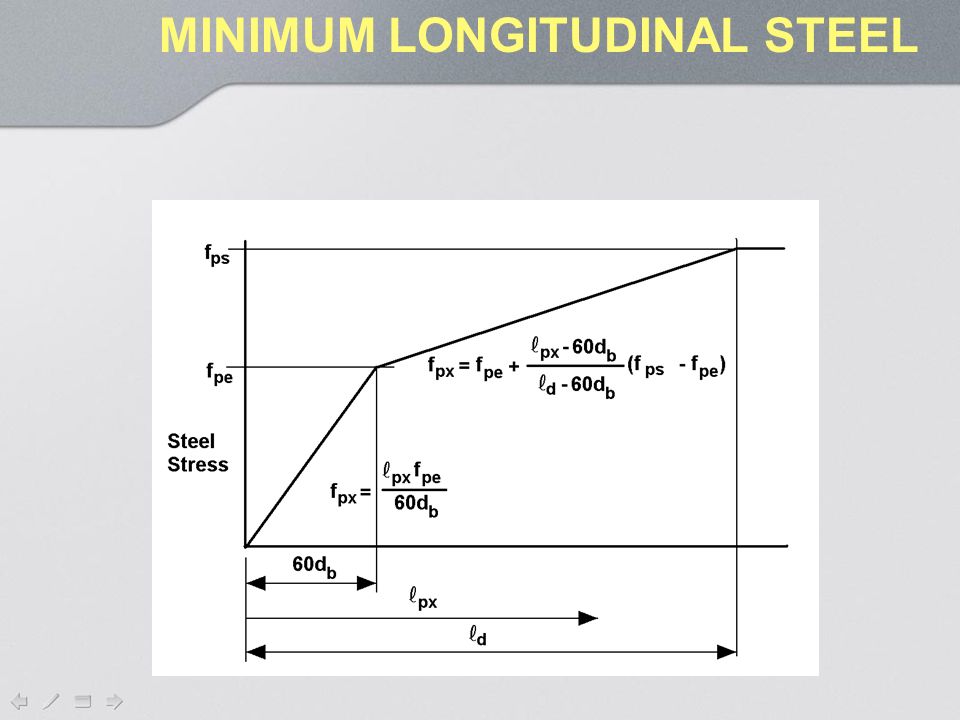
MINIMUM LONGITUDINAL STEEL As noted earlier, the compression forces in the concrete strut generate tensile forces in the longitudinal steel. It is possible that these tensile forces might be great enough, when combined with the tensile forces due to moment and axial load, to fail the longitudinal tensile steel. Therefore, a check must be made to assure that there is sufficient tensile steel to resist all the forces.

43
The minimum tension the longitudinal steel must resist is: Note that is the appropriate strength reduction factor for the load effect (e.g. 0.9 for Mu in reinforced concrete). V s < V u / MINIMUM LONGITUDINAL STEEL
. V s < V u / MINIMUM LONGITUDINAL STEEL.")
44
The tension, “T” must be less than the resistance of the longitudinal steel: Note that the steel is only that which is on the flexural tension side of the member. Also, f y and f ps must be reduced for lack of development (e.g. if the mild steel extends only ½ L d past the critical section, the allowable stress is reduced to ½ f y ; where L d is the development length). MINIMUM LONGITUDINAL STEEL
. MINIMUM LONGITUDINAL STEEL.")
45
The code says that this provision does not apply to sections where there is a compression reactions at the compressive face of the beam (i.e. reactions at the bottom of the beam in a negative moment zone at an interior support.). In these cases the minimum longitudinal steel is that required to resist Mu / . This provision applies to this example over the supports, but not at the critical section which is 73” from the support. MINIMUM LONGITUDINAL STEEL
. In these cases the minimum longitudinal steel is that required to resist Mu / . This provision applies to this example over the supports, but not at the critical section which is 73 from the support. MINIMUM LONGITUDINAL STEEL.")
46
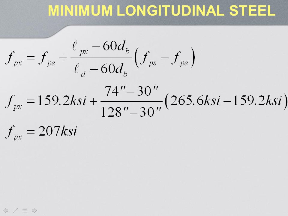
Step 1: Find the development length of the prestressing steel: f ps is the steel stress at ultimate in the prestressing steel, f ps is the effective steel stress and d b is tendon diameter. MINIMUM LONGITUDINAL STEEL

47
Step 2: Find the length of harped tendons at the critical section = d v : L = dv / cos = 73.25/cos 7.2º = 74” This is less than the development length of 128”, so reduce the allowable stress in the strand. LRFD allows the use of the bi-linear curve shown on the next slide defined by this equation: MINIMUM LONGITUDINAL STEEL

50
There are 12 harped strands on the flexural tension side of the beam. MINIMUM LONGITUDINAL STEEL

51
Check horizontal shear. Note that the horizontal shear is caused only by composite loads! Calculate composite shear at the critical section: V u1 = 1.25DC+1.5DW+1.75LL = 1.25(7.8) + 1.50(14.2)+1.75(137.3) = 271.3k So: (5.8.4.2-1) HORIZONTAL SHEAR
 (14.2)+1.75(137.3) = 271.3k So: ( ) HORIZONTAL SHEAR.")
52
What is v ci ? It is the average shear stress at the interface/unit length of beam. v ci HORIZONTAL SHEAR

53
T2T2 T1T1 C2C2 C1C1 M1M1 V1V1 M2M2 V 1 + V LL M 2 = M 1 + V1 L HORIZONTAL SHEAR

54
T2T2 T1T1 C2C2 C1C1 M1M1 V1V1 M2M2 V 1 + V LL HORIZONTAL SHEAR C 2 = M 2 / d v = M 1 /d v + V 1 L/d v C1 = M 1 / d v

55
T2T2 T1T1 C2C2 C1C1 M1M1 V1V1 M2M2 V 1 + V LL HORIZONTAL SHEAR If the horizontal shear = C 2 – C 1 : V h = V 1 L/d v

56
T2T2 T1T1 C2C2 C1C1 M1M1 V1V1 M2M2 V 1 + V LL HORIZONTAL SHEAR Average stress = v ci = V h /(b vi L) v ci = V 1 L/(b vi L d v ) = V 1 /(b vi d v )
 v ci = V 1 L/(b vi L d v ) = V 1 /(b vi d v )")
57
(5.8.4.2-2) The top of the girder is 42 inches wide. The minimum stirrups are #5@24in, so if L vi = 24 inches: HORIZONTAL SHEAR

58
The nominal shear resistance of the interface plane is: Where: c =Cohesion factorksi [LRFD 5.8.4.3] μ =Friction factor Acv =Area of concrete engaged in shear transfer = bviLviin2 Avf =Area of shear reinforcement crossing the shear planein2 Pc =Permanent net compressive force normal to the shear planekips fy =Shear reinforcement yield strengthksi bvi=Width of area of concrete engaged in shear transferin Lvi =Length of area of concrete engaged in shear transferin (5.8.4.1-1) (5.8.4.1-3) The allowable interface shear is: HORIZONTAL SHEAR
![The nominal shear resistance of the interface plane is: Where: c =Cohesion factorksi [LRFD ] μ =Friction factor Acv =Area of concrete engaged in shear transfer = bviLviin2 Avf =Area of shear reinforcement crossing the shear planein2 Pc =Permanent net compressive force normal to the shear planekips fy =Shear reinforcement yield strengthksi bvi=Width of area of concrete engaged in shear transferin Lvi =Length of area of concrete engaged in shear transferin ( ) ( ) The allowable interface shear is: HORIZONTAL SHEAR](http://images.slideplayer.com/34/8322218/slides/slide_58.jpg "The nominal shear resistance of the interface plane is: Where: c =Cohesion factorksi [LRFD ] μ =Friction factor Acv =Area of concrete engaged in shear transfer = bviLviin2 Avf =Area of shear reinforcement crossing the shear planein2 Pc =Permanent net compressive force normal to the shear planekips fy =Shear reinforcement yield strengthksi bvi=Width of area of concrete engaged in shear transferin Lvi =Length of area of concrete engaged in shear transferin ( ) ( ) The allowable interface shear is: HORIZONTAL SHEAR")
59
For a cast-in-place concrete placed against clean concrete girder surfaces, free of laitance with surface intentionally roughened to an amplitude of 0.25 in: c = 0.28 = 1.0 (5.8.4.2) HORIZONTAL SHEAR
 HORIZONTAL SHEAR")
60
Begin by exploring what happens when the shear reinforcement is the minimum used anywhere in the girder. The shear reinforcement was previously calculated to be #5 @ 24 inches minimum. The shear width is b vi = 42 inches as this is the width of the top of the girder. If L vi = 24 inches: HORIZONTAL SHEAR

Similar presentations