Download presentation
Presentation is loading. Please wait.

1
Engineering Graphics III – Pictorial Projections Prof. Jon Southen October 15, 2008

2
Pictorial Projections Text Reference: Bertoline-Wiebe, Fundamentals of Graphics Communication, Chapter 7

3
Orthographic Projections Multiview Drawings Discussed last class Show two dimensions at a time (with proper size and shape) Images must be mentally combined to form full 3-D description of object Pictorial Views Show all three dimensions at once, making visualization easier
 Images must be mentally combined to form full 3-D description of object Pictorial Views Show all three dimensions at once, making visualization easier")
4
Pictorial Views Pictorial views show all three dimensions in one view Common projections: Perspective Oblique (Cabinet) Axonometric (Isometric)
 Axonometric (Isometric)")
7
Perspective Views

10
Oblique Projection Front view is true size and shape Not a true projection – CAD can’t generate them Other dimensions are greatly distorted

11
Oblique Projection

13
Practice - Oblique View

14
Axonometric Projection

17
Axonometric (isometric) All lengths to same scale Not true shape Angles equal CAD can generate isometric views 60º
 All lengths to same scale Not true shape Angles equal CAD can generate isometric views 60º")
18
Scale and Axes “Full-scale”: All dimensions same as those on equivalent multiview drawings Coordinate axes separated by 120 degrees (2:1 on squared paper)
")
19
Creating Isometric Drawings Determine viewpoint that most clearly depicts features of object Construct isometric box that contains the object Locate details on isometric planes Darken visible lines

20
Front Top Side

21
Practice – Isometric View

22
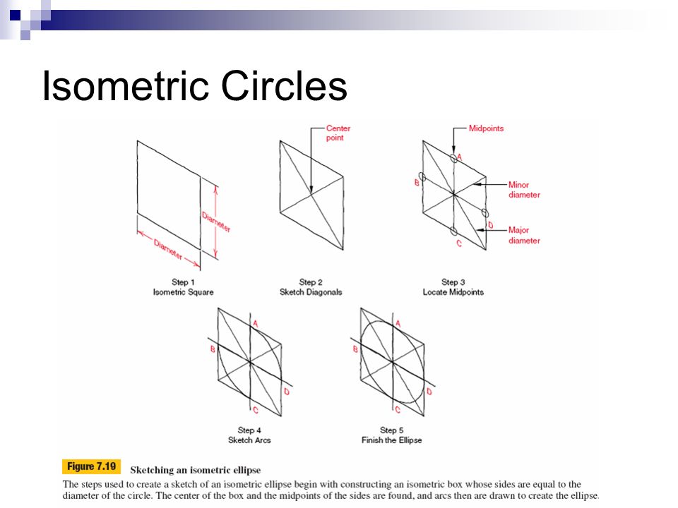
Isometric Circles

24
Standards for Isometric Drawings Show hidden lines only if absolutely necessary to describe the object Show centerlines only to show symmetry or for dimensioning Isometric view not normally dimensioned Guidelines for sketching other features (ellipses, curves, etc.) may be found in the text
 may be found in the text")
25
Isometric Sketching

27
Example: Sketch Isometric View

28
Sketch Isometric View http://pergatory.mit.edu/2.007/resources/drawings/index.html

29
Multiview Drawing Visualization Reading an engineering multiview drawing requires one to form a clear 3-D mental image of the object.

30
To improve visualization skills Study existing drawings Construct physical models Contrast similar shapes

35
What is Isometric View?

36
Possible Solutions

37
Adjacent Areas Surfaces which reside next to each other Boundary between surfaces represented by line indicating change of planes No two can lie in same plane

38
Adjacent Areas represent 1. Surfaces at different levels 2. Inclined or oblique surfaces 3. Cylindrical surfaces or arc 4. A combination of these

40
Next Class Other Views Dimensioning and Tolerancing

Similar presentations


>")


