Download presentation
Presentation is loading. Please wait.

1
8259A PROGRAMMABLE INTERRUPT CONTROLLER

2
CONTINUE…. The 8259A consist of eight data bus lines from D0-D7 The data bus is the path over which data are transferred between MPU and 8259A. The data can be command words, status information or interrupt type numbers. The control signals WR and RD (active low) logic 0, signal the 8259A whether data to be written or read from its internal register. The CS (active low) to enable the host interface enable. A0 input involved in he selection of internal register that is accessed during read and write operations. Interrupt request IR0-IR7 inputs are issued by external devices for service
 logic 0, signal the 8259A whether data to be written or read from its internal register. The CS (active low) to enable the host interface enable. A0 input involved in he selection of internal register that is accessed during read and write operations. Interrupt request IR0-IR7 inputs are issued by external devices for service.")
3
CONTINUE… CAS0-CAS2 are known as cascade interface. The cascade lines are used to cascaded system where number of 8259A ICs are interconnected in master/slave configuration to expand the number of IR inputs from 8 to as high as 64. SP/EN (active low) is used to indicate the current device acts as a master or slave. INT is the interrupt request output of 8259A. It is applied directly to the INTR input of the 8086. Logic 1 is produced at this output whenever the interrupt controller receives a valid request from an interrupting device. INTA (active low) is an input pin of the 8259A. This pin is used to receive acknowledgement
 is used to indicate the current device acts as a master or slave. INT is the interrupt request output of 8259A. It is applied directly to the INTR input of the Logic 1 is produced at this output whenever the interrupt controller receives a valid request from an interrupting device. INTA (active low) is an input pin of the 8259A. This pin is used to receive acknowledgement.")
4
INTERRUPT REQUEST REGISTER Interrupt request register keeps track of which interrupt inputs are asking for service If an interrupt input has an interrupt signal on it, then corresponding bit in the interrupt request register will be set.

5
INTERRUPT MASK REGISTER Interrupt mask register is used to disable or enable the individual interrupt inputs. Each bit in this register corresponds to the interrupt input with the same number.

6
IN-SERVICE REGISTER The In-service register keep tracks of which interrupt inputs are currently being serviced The corresponding bit will be set in the in service register.

7
PRIORITY RESOLVER The priority resolver acts as a “judge” that determines if and when an interrupt request on one of the IR inputs get serviced.

8
PROGRAMMING THE 8259A The way in which the 8259A operates is determined by how the device is programmed. Two types of command words are provided for the programming of 8259A. ICW (Initialization Command words) OCW( Operational Command Words)
 OCW( Operational Command Words).")
10
ICW ICW commands are used to load the internal control registers of the 8259A to define the basic configuration or mode in which it is used. There are four command words identified as ICW1 ICW2 ICW3 ICW4 OCW are needed for 8086 microprocessor to initiate variation in the basic operating modes defined by the ICW commands. OCW1,OCW2,OCW3.

11
ICW1

12
ICW1 BITS A0=0 and D4=1 bit is set indicates the ICW1. D0 bit indicates ICW4 is needed or not. 1=ICW4 needed 0=no ICW4 needed. D1=1 single mode D1=0 cascade mode LTIM=1 Level Triggered Input LTIM=0 Edge Triggered Input In 8086 mode D5,D6,D7 are don’t care conditions.

13
ICW2 In 8086 system, ICW2 is used to tell the 8259A the type number to send in response to an interrupt signal on IR0 input. In response to an interrupt signal on some other IR input, the 8259A will automatically add the number of IR input to the base number and send the result to the 8086 as the type number for that input.

14
ICW2

15
ICW3 ICW3 is needed when 8259A is working in a cascade mode of operation. ICW3 is used in a different function based on 8259A is working as master or slave. If it is master the bits D7-D0 are labeled as S7-S0. If it is slave the device load with a 3-bit identification code ID2,ID1,ID0.

17
ICW4 ICW4 is used when the device is configured with the 8088 or 8086. When PU bit is set to 1 indicates the working with 8086. AEOI MS BUF SFNM

19
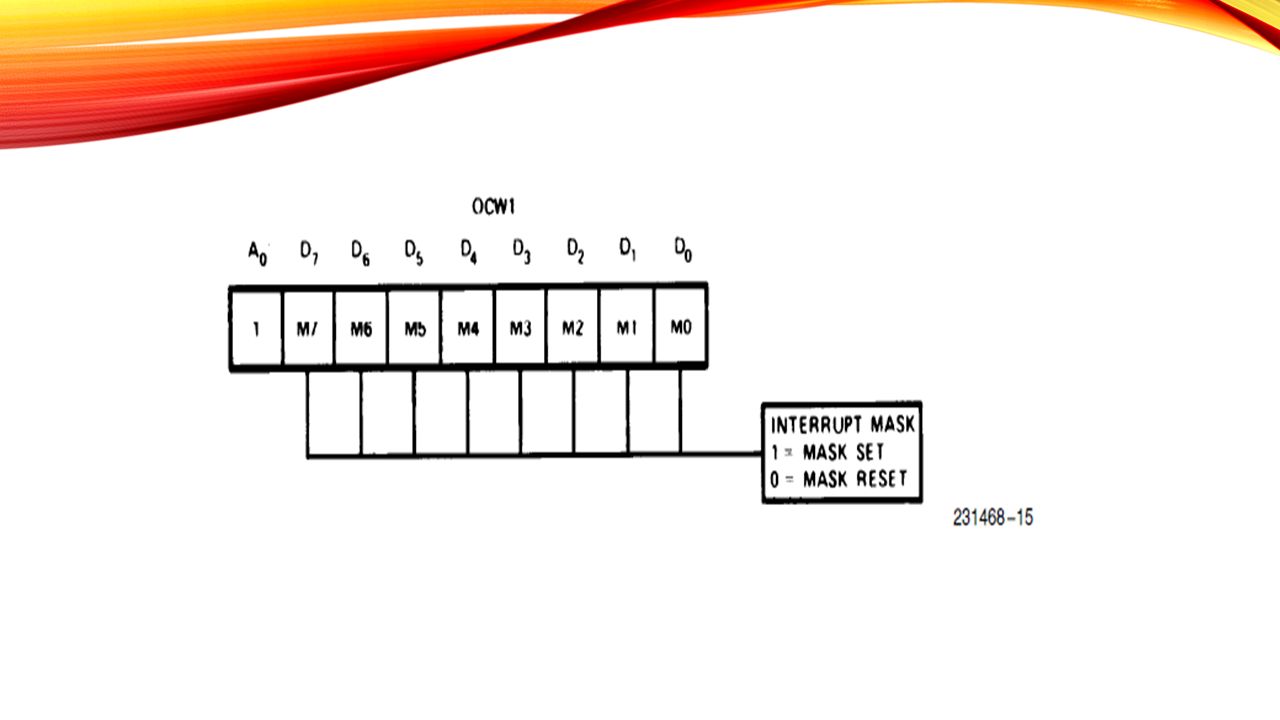
OPERATIONAL COMMAND WORDS OCW are used to provided for controlling the operation of 8259A. The OCW1 is used to access the contents of mask register. This permits the selective masking of interrupt inputs.

21
OCW2 The OCW2 selects the appropriate priority scheme and assigns an IR level scheme that requires a specific interrupt level. It is used to reset bit in the in-service register

23
OCW3 It permits the reading of the contents of ISR or IRR registers through software.

25
MODES OF OPERATIONS 1>Fully nested mode 2>special fully nested mode. 3>nonspecific rotating mode. 4>specific rotating mode. 5>special mask mode. 6>polled mode.

26
INTERFACING 5259

Similar presentations


>")


 is needed. Sources of interrupts: internal fault (e.g.. divide by.>")
 is needed. Sources of interrupts: internal fault (e.g.. divide by.>")
>")

>")


