Download presentation
Presentation is loading. Please wait.

1
UNIVERSITY OF CENTRAL FLORIDA DEPARTMENT OF MECHANICAL, MATERIALS AND AEROSPACE ENGINEERING Reverse Turbo Brayton Cryo-Cooler Development Miniature Engineering Systems Group

2
INITIAL ANALYSIS ABOUT THE SUITABILITY OF GAS-FOIL BEARINGS TO OUR SYSTEM Presented by – K.V.Krishna Murty

3
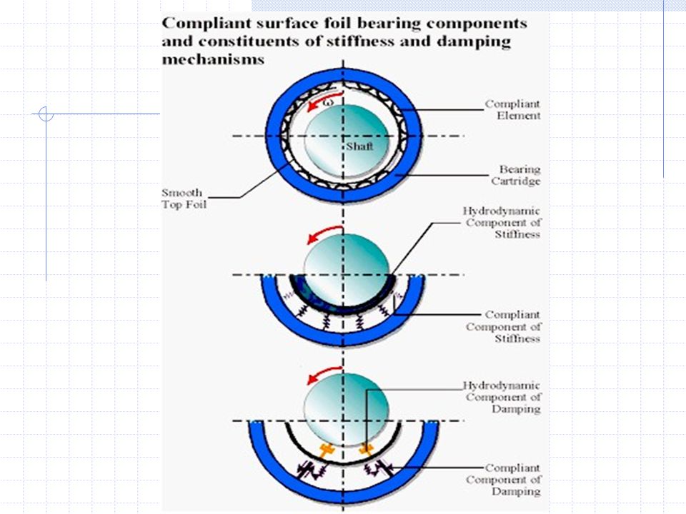
Principle : Gas-Foil bearings While the shaft is stationary, there is a small amount of preload between the shaft and the bearing. As the shaft turns, a hydrodynamic pressure is created, that pushes the foils away from the shaft and makes the shaft completely gas/airborne. This phenomenon occurs instantly during start-up at a very low speed i.e., at about speeds of 4.16% of the maximum rotational speed of the shaft(when tested by MiTi in a foil bearing test rig). When the shaft is airborne, the frictional loss due to shaft rotation is quite small. As the shaft grows, the foils get pushed farther away, keeping the film clearance relatively constant. And in addition, the foils provide a coulomb damping due to their relative sliding. This damping is essential for the stability of the machine.
. When the shaft is airborne, the frictional loss due to shaft rotation is quite small. As the shaft grows, the foils get pushed farther away, keeping the film clearance relatively constant. And in addition, the foils provide a coulomb damping due to their relative sliding. This damping is essential for the stability of the machine..")
4
Initial stage Configuration at higher speeds FIGURES: Leaf-foil gas bearing

5
FIGURES: Bump-foil gas bearing Initial configuration Configuration at high speeds

7
Advantages: 1) Soft failure. 2) Higher load bearing capacity at higher speeds. 3) Operate efficiently at cryogenic temperatures. 4) No oily lubricants and hence no contamination.
 Operate efficiently at cryogenic temperatures. 4) No oily lubricants and hence no contamination..")
8
Disadvantages: The major obstacle would be during start-up and at stop because of friction. The shaft would be in direct contact with the foils until it reaches a speed of about 6300 rpm(usually depends on the gas pressure and the shaft material) for a motor spinning at 150,000 rpm.
 for a motor spinning at 150,000 rpm..")
9
Load Capacity Estimation of Foil Gas Bearings: W = D’ (L x D) (D x s) where ; W is the maximum steady-state load that can be supported, N D’ is the bearing load capacity coefficient, N/(mm 3 krpm) L is the bearing axial length, mm D is the shaft diameter, mm s is the shaft speed in thousand rpm
 (D x s) where ; W is the maximum steady-state load that can be supported, N D’ is the bearing load capacity coefficient, N/(mm 3 krpm) L is the bearing axial length, mm D is the shaft diameter, mm s is the shaft speed in thousand rpm")
10
Future research plan : To design the foil/bump contour and number of foils/bumps required so as to minimize the start-up and stop friction (including modeling and analysis). To calculate the losses associated and hence the efficiency. Testing.

11
Foil Air Bearings – Product Survey: Miniature foil bearing designed for cryogenic helium compressor – courtesy Foster-miller Technologies. Foil Air Bearings developed at NASA.

12
References: 1) Technical paper (97-GT-347) written By Giri L. Agrawal for ASME International's 1997 International Gas Turbine & Aero engine Congress & Exhibition in Orlando, FL. 2) Load Capacity Estimation of Foil Air Journal Bearings for Oil-Free Turbo machinery Applications, NASA/TM-2000- 209782, Oct 01, 2000. 3) Information and Publications Office, MS 8–1, Glenn Research Center - NASA. 4) MiT Inc.,. News letter - Compliant Foil Bearing Supports Steady Load of 942 pounds - Winter 1998Compliant Foil Bearing Supports Steady Load of 942 pounds - Winter 1998
 Load Capacity Estimation of Foil Air Journal Bearings for Oil-Free Turbo machinery Applications, NASA/TM , Oct 01, ) Information and Publications Office, MS 8–1, Glenn Research Center - NASA. 4) MiT Inc.,. News letter - Compliant Foil Bearing Supports Steady Load of 942 pounds - Winter 1998Compliant Foil Bearing Supports Steady Load of 942 pounds - Winter")
Similar presentations


>")


 Pivot Stiffness on Tilting Pad Bearing Dynamic Force Coefficients – Analysis Jared Goldsmith Research Assistant Dr.>")


