Download presentation
Presentation is loading. Please wait.

1
References Hans Kuzmany : Solid State Spectroscopy (Springer) Chap 5 S.M. Sze Physics of semiconductor devices (Wiley) Chap 13 PHOTODETECTORS
 Chap 13 PHOTODETECTORS.")
2
Detection of Electromagnetic radiation Signal and Noise Photomultipliers Photoelectric Detectors

3
Signal and Noise for photon counting Low signal/noise ratio 23/4 = 6.5 Scattering experiment S= signal N = noise B = background D = dark level

4
Signal and Noise Low probability event Signal = photon absorption Scattering Absorption Probability of absorption, i.e. contribution to signal= p Probability = q =1-p For coins p=q=1/2 For photons……. p <<q Origin of Noise at detector

5
Signal and Noise Signal = photon absorption n incident photons Probability of no absorption q =1-p Binomial distribution k adsorbed photons Probability of 1 photon absorption = p Probability absorption of k photons Or no contribution to signal

6
Signal and Noise For photons……. p <<q np = expected value Poisson distribution n = 200 p = 0.05 k = 10 k = mean value of k

7
If I have 200 photons every sec, for every second the absorbed photon number might be 7,9,10,15, depending on the probability distribution, but on average I have 10 photons absorbed per sec. For large n, np k So is the average magnitude of the signal By increasing the measuring time (or equivalently increasing the number of incident photons ) the magnitude increases linearly, and the noise increases as square root, so the signal to noise ration gets better as T The noise intensity is defined as the variance of the Poisson distribution So the signal is on average 10
 the magnitude increases linearly, and the noise increases as square root, so the signal to noise ration gets better as T The noise intensity is defined as the variance of the Poisson distribution So the signal is on average 10 .")
8
PHOTOMULTIPLIERS Elements: Photocathode Dynodes Anode e-e- Operation: Photocathode animation Photon in Photocathode e - emission e- on dynode Secondary e - emission Current on Anode http://micro.magnet.fsu.edu/primer/java/digitalimaging/photomultiplier/sideonpmt/index.html

9
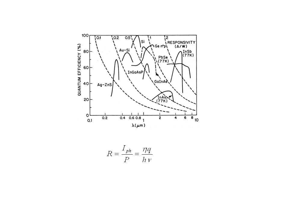
Photocathode Material to emit electrons by photoelectric effect Key property: low work function to allow extraction of e - The photon absorption depend on the material Hence the photocathodes are sensible to some part of the light spectrum Quantum efficiency

10
Radiation sensitivity Typical 80 mA/W I c = current at photocathode P = incident light power

11
Dark current Due to thermal emission of electrons M = material dependent factor ( 0.5) T = temperature W = material work function (1.5-3 eV) J(T) increases rapidly with T, so photocathode needs to be cooled if you need to observe few e/s
 T = temperature W = material work function (1.5-3 eV) J(T) increases rapidly with T, so photocathode needs to be cooled if you need to observe few e/s")
12
Dynodes The dynodes work by employing secondary electron emission (SEE) SEE: When a primary beam hits a surface, then it generates electrons that are either emitted either travel into the solid and generate more electrons
 SEE: When a primary beam hits a surface, then it generates electrons that are either emitted either travel into the solid and generate more electrons")
13
Secondary Electron Eemission Physical principle: ionization of a solid (atom) by an electron with kinetic energy E 0 Each scattering event might generate one or more e - Secondary Electron Yield I 0 = incident beam current I S = secondary current (I emitted from surface) E 0 = [1 10 6 eV]
![Secondary Electron Eemission Physical principle: ionization of a solid (atom) by an electron with kinetic energy E 0 Each scattering event might generate one or more e - Secondary Electron Yield I 0 = incident beam current I S = secondary current (I emitted from surface) E 0 = [1 10 6 eV]](http://images.slideplayer.com/33/8235613/slides/slide_13.jpg "Secondary Electron Eemission Physical principle: ionization of a solid (atom) by an electron with kinetic energy E 0 Each scattering event might generate one or more e - Secondary Electron Yield I 0 = incident beam current I S = secondary current (I emitted from surface) E 0 = [1 10 6 eV]")
14
Secondary Electron Eemission Contributions I e = elastically scattered e - I 0 = incident beam current I S = secondary current (I emitted from surface) E 0 = [1 10 6 eV] I r = rediffused e - I ts = true secondary e -
![Secondary Electron Eemission Contributions I e = elastically scattered e - I 0 = incident beam current I S = secondary current (I emitted from surface) E 0 = [1 10 6 eV] I r = rediffused e - I ts = true secondary e -](http://images.slideplayer.com/33/8235613/slides/slide_14.jpg "Secondary Electron Eemission Contributions I e = elastically scattered e - I 0 = incident beam current I S = secondary current (I emitted from surface) E 0 = [1 10 6 eV] I r = rediffused e - I ts = true secondary e -")
15
Collect the current by applying a voltage V so that only e - with E K E = eV arrives at detector The signal is the sum (integral) over the electrons up to the maximum E K Usually we are interested in the value of S for a range of energy and to get N(E) we must differentiate the signal Electron Energy (eV) N(E) E0E0 E 0 + ΔE
 over the electrons up to the maximum E K Usually we are interested in the value of S for a range of energy and to get N(E) we must differentiate the signal Electron Energy (eV) N(E) E0E0 E 0 + ΔE")
16
For dynodes all the current originated from secondary emission is used The number of dynodes n provides the multiplication factor G (gain) of the photomultiplier Typical values = 5, n = 10 G = 5 10 10 7 G depends on the voltage because the voltage sets the primary energy of the incident e - generated in the dynode
 of the photomultiplier Typical values = 5, n = 10 G = 5 10 10 7 G depends on the voltage because the voltage sets the primary energy of the incident e - generated in the dynode")
17
Slab of semiconductor between two electrodes PHOTOELECTRIC DETECTORS Generation of carriers: intrinsic = mobility n,p = concentration q = charge For < c incident radiation is adsorbed Generation of carriers: extrinsic The cutoff is determined by the energy of donor and acceptor states Performance detemined by: gain, response time, sensitivity

18
Principle of operation n 0 = density of carriers generated by a photon flux at t=0 Recombination processes P = optical power n(t) = density of carriers at time t = carrier lifetime At steady state, the carrier generation rate is equal to recombination rate 1/ = recombination rate Total number of photons impinging on the surface/unit time is P/h Generation rate = quantum efficiency PHOTOELECTRIC DETECTORS Steady, uniform photon flux on A=wL
 = density of carriers at time t = carrier lifetime At steady state, the carrier generation rate is equal to recombination rate 1/ = recombination rate Total number of photons impinging on the surface/unit time is P/h Generation rate = quantum efficiency PHOTOELECTRIC DETECTORS Steady, uniform photon flux on A=wL")
19
The current due to photon absorbption The gain of the device depends on carrier lifetime and carrier velocity Defining primary photocurrent as Carrier Transit time

20
depends on absorption coefficient PHOTODIODES Depleted semiconductor High E to separate photogenerated e - -h pairs Depletion region small to reduce t r Depletion region large to increase Reverse bias to reduce t r

Similar presentations


 light emitted during electronic recombination in the scintillator. Therefore, the spectrum collected.>")

 University of Palermo –DEIM A.A. 2014-15.>")


 Energy (J) Irradiance (W/m 2 ) Emittance (W/m 2 ) Intensity (W/sr) Radiance (W/sr m 2 )>")
>")


 The characteristic lines are a result of electrons ejecting orbital.>")

.>")
