Download presentation
Presentation is loading. Please wait.

1
Photomultiplier Tube m = k 8–19 dynodes (9-10 is most common).
Gain (m) is # e- emitted per incident e- () to the power of the # of dynodes (k). m = k E.g., 5 e- emitted / incident e-, 10 dynodes. m = k = 510 1 x 10⁷ Typical Gain = Douglas A. Skoog and James J. Leary, Principles of Instrumental Analysis, Saunders College Publishing, Fort Worth, 1992.
 is # e- emitted per incident e- () to the power of the # of dynodes (k). m = k. E.g., 5 e- emitted / incident e-, 10 dynodes. m = k = 510 1 x 10⁷. Typical Gain = Douglas A. Skoog and James J. Leary, Principles of Instrumental Analysis, Saunders College Publishing, Fort Worth,")
2
Choosing a PMT Average anodic current Single photon counting
Hamamatsu Catalog

3
Modes of Operations Average anodic current Single photon counting
Hamamatsu Catalog

4
Single Photon Counting
Single photons give bursts of e- The rise time of PMTs depends on the spread in the transit time of e- during the multiplication process. FWHM: Full Width at Half of Maximum Hamamatsu Catalogue

5
Single Photon Counting
Improved S/N at low p Hamamatsu Catalogue

6
Thermionic Emission is Dependent on Bias Voltage
Hamamatsu Catalogue

7
Sources of Dark Current: Glass Scintillation
Brief flash of light when an e- strikes the glass envelope. Douglas A. Skoog and James J. Leary, Principles of Instrumental Analysis, Saunders College Publishing, Fort Worth, 1992. Ingle and Crouch, Spectrochemical Analysis

8
Sources of Dark Current: Thermionic Emission
Thermal energy releases e- from the cathode. Reduced by cooling Hamamatsu Catalogue

9
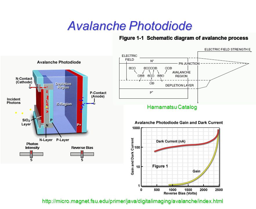
Photodiodes Photons incident on the depletion layer induce a current.
In most cases, best response in the NIR. Response is linear over 6 – 7 orders of incident radiant power Ingle and Crouch, Spectrochemical Analysis

10
Semiconductors Silicon or Germanium are common.
n-type: Si (or Ge) doped with group V element (As, Sb) to add electrons. p-type: Doped with group III element (In, Ga) to add holes. J. Michael Hollas, Modern Spectroscopy, John Wiley & Sons, New York, 1992.
 doped with group V element (As, Sb) to add electrons. p-type: Doped with group III element (In, Ga) to add holes. J. Michael Hollas, Modern Spectroscopy, John Wiley & Sons, New York,")
11
Diode (pn – Junction) Douglas A. Skoog and James J. Leary, Principles of Instrumental Analysis, Saunders College Publishing, Fort Worth, 1992.

12
Spectral Response of Photodiodes
Shinya Inoue and Kenneth Spring, Video Microscopy, Plenum Press, New York, 1997.

13
Avalanche Photodiode Hamamatsu Catalog
14
Photodiode Arrays (PDA or DAD)
Simultaneous detection in a spectrophotometer. Douglas A. Skoog and James J. Leary, Principles of Instrumental Analysis, Saunders College Publishing, Fort Worth, 1992.

15
Charge Coupled Device (CCD)
Ingle and Crouch, Spectrochemical Analysis

16
CCD Architecture Image Area Top View SiO2 backing Pixel Array
insulating oxide Image Area Top View serial register amplifier and Bryce Marquis (Haynes Lab)
![]()
17
Bryce Marquis (Haynes Lab)
CCD Architecture “Channel Stops” form horizontal pixel boundaries Top View 3 electrodes form vertical pixel boundaries One pixel Electrode Insulating oxide n-type silicon p-type silicon Cross section Bryce Marquis (Haynes Lab)
")
18
Charge Generation/Collection
-V +V -V -V +V -V N-type P-type Incident photons excite electron-hole pairs, electrons gather in potential wells in each pixel

19
CCD Rain Bucket Analogy
1. Generation 2. Collection 3. Transfer 4. Measurement Shinya Inoue and Kenneth Spring, Video Microscopy, Plenum Press, New York, 1997.

20
Charge Transfer Every third electrode is 2 coupled, charge packets
are walked towards serial registry 2 +5V 0V -5V 1 +5V 0V -5V 3 to serial registry 1 2 3 Time-slice shown in diagram

21
+5V 0V -5V 2 +5V 0V -5V 1 +5V 0V -5V 3 1 2 3

22
+5V 0V -5V 2 +5V 0V -5V 1 +5V 0V -5V 3 1 2 3

23
+5V 0V -5V 2 +5V 0V -5V 1 +5V 0V -5V 3 1 2 3

24
+5V 0V -5V 2 +5V 0V -5V 1 +5V 0V -5V 3 1 2 3

25
+5V 0V -5V 2 +5V 0V -5V 1 +5V 0V -5V 3 1 2 3

26
+5V 0V -5V 2 +5V 0V -5V 1 +5V 0V -5V 3 1 2 3

27
Charge Transportation
amplifier Pixels at end of the array dump charge into serial register Serial register walks charge packets to amplifier, where it is measured.

28
Quantum Efficiency

29
Noise Sources in CCD Shot Noise Dark Signal Noise Readout Noise
Statistical variation of signal over time Increases with the square of the intensity Dark Signal Noise Caused by thermal liberation of electrons Strongly coupled to temperature Readout Noise Summation of noise associated with amplification of signal, and conversion from analogue to digital Increases with the processing speed

30
Other Issues: Bad Pixels
Increasing hot pixels Hot Pixels Increased charge accumulation due to variations in chip surface. Dead Pixels Defective pixels that do not respond.
![]()
31
Other Issues: Blooming

32
Other Issues: Cosmic Rays
Noise From Outer Space!!! * indicates cosmic rays

33
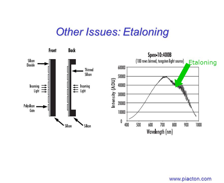
Other Issues: Etaloning
34
Other Features: Binning
On Chip Pixel Binning Increases S/N Shot noise decrease Increased speed Less storage space needed Decreases resolution

35
Are you getting the concept?
List the advantages and disadvantages of using each of the discussed detectors to achieve single molecule detection.

Similar presentations


 Heated electrically to 1300 – 1500 K Positive temperature coefficient of resistance.>")


 BUCKETS (PIXELS) VERTICAL CONVEYOR BELTS (CCD COLUMNS) HORIZONTAL CONVEYOR BELT ( SERIAL REGISTER ) MEASURING CYLINDER (OUTPUT AMPLIFIER)>")

>")


 Identify m of real source and adjust T in to line up m 2) The ratio of: 3) Measure T w ( ) to calculate ( ) Ingle and Crouch,>")


 What characteristics should we look for in a transducer?>")


