Download presentation
Presentation is loading. Please wait.

1
Introduction to Transportation Engineering Alignment Design Vertical Alignment Instructor Dr. Norman Garrick Hamed Ahangari May 2014

2
Basic Elements Horizontal Alignment Vertical Design Cross Section

3
3 Horizontal Alignment Vertical Alignment Crest Curve Sag Curve G1G1 G2G2 G3G3

4
Design of Vertical Curves

5
Parabolic Curve 5 BVC EVC L G2G2 G1G1 L/2 PI Change in grade: A = G 2 - G 1 G is expressed as % Rate of change of curvature: K = L / |A| Rate of change of grade: r = (g 2 - g 1 ) / L Equation for determining the elevation at any point on the curve y = y 0 + g 1 x + 1/2 rx 2 where, y 0 = elevation at the BVCg = grade expressed as a ratio x = horizontal distance from BVCr = rate of change of grade (ratio)
 / L Equation for determining the elevation at any point on the curve y = y 0 + g 1 x + 1/2 rx 2 where, y 0 = elevation at the BVCg = grade expressed as a ratio x = horizontal distance from BVCr = rate of change of grade (ratio)")
6
A B El. 100 ` 140 120 130 110 150 170 180 190 160 El. 200

7
Alignment Standard related to Design Speed Design Speed (mph) Minimum Radius of Horizontal Curve (ft) Maximum Percentage of Grade Minimum Length of Vertical Curve for each 1% of Algebraic Differences 201001210 302501020 40450835 50750770 6011005150 7016004200 Site Engineering by Steven Storm
 Minimum Radius of Horizontal Curve (ft) Maximum Percentage of Grade Minimum Length of Vertical Curve for each 1% of Algebraic Differences Site Engineering by Steven Storm")
8
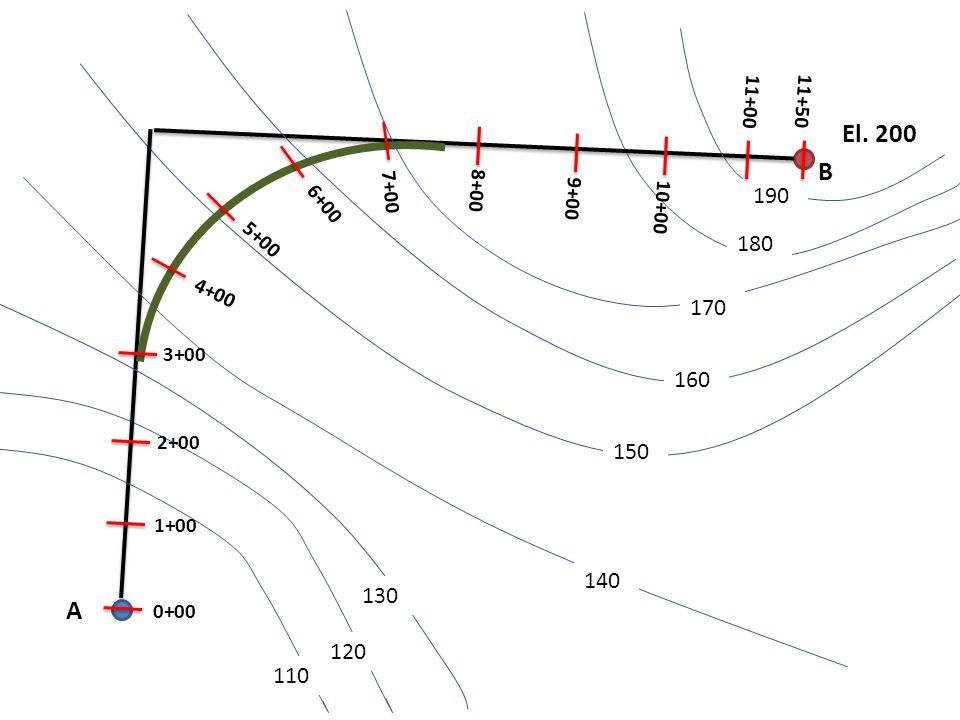
` A B El. 200 El. 100 140 120 130 110 170 160 150 180 190

9
` A B El. 200 120 150 180 130 170 110 140 160 190 0+00 1+00 2+00 3+00 4+00 5+00 6+00 7+00 8+00 9+00 10+00 11+50 11+00
10
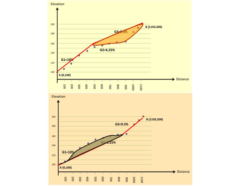
Longitude Profile Distance Elevation 100200 300400500600 700800 900 10001100 100 120 140 160 180 200 B (1150,200) A (0,100)
 A (0,100)")
11
Distance 100200 300400500600 700800 900 10001100 100 120 140 160 180 200 B (1150,200) A (0,100) Elevation G1=10% h=40’,d=400’ h=20’,d=320’ G2=6.25% h=40’,d=430’ G3=9.3%
 A (0,100) Elevation G1=10% h=40’,d=400’ h=20’,d=320’ G2=6.25% h=40’,d=430’ G3=9.3%")
12
Distance 100200 300400500600 700800 900 10001100 100 120 140 160 180 200 B (1150,200) A (0,100) Elevation G1=10% G2=6.25% G3=9.3%
 A (0,100) Elevation G1=10% G2=6.25% G3=9.3%")
14
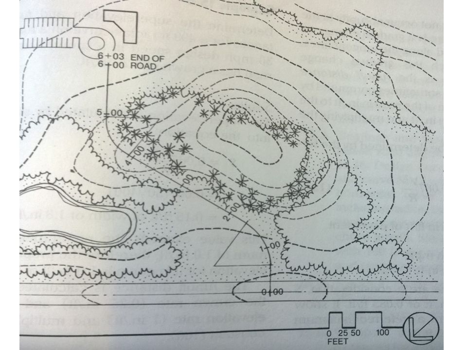
Vertical alignment Step 1: First provide the longitude profile of the road which contain earth elevations. Step 2: Based on the maximum allowable slope and topographic condition, determine vertical tangents. Step 3: Calculate the parabolic vertical curve specifications.

15
Example We want to design a road which connect point A and B Design Speed is 30 mph Provide vertical alignment for this road

16
` A B

Similar presentations


>")


>")
 You learned how to lay out a vertical curve, given grades, PVC, PVI, and PVT in CE113 Surveying.>")


