Download presentation
Presentation is loading. Please wait.

1
Pulse-Height Analyzers Basic Functions Single Channel Analyzers Time Methods Multi-channel Analyzers

2
Basic Function The amplitude of output signal is proportional to the energy of the radiation event detected Selective counting of those pulses within certain amplitude resulted in counting of selective energy range A certain energy range or interval is called energy channel

3
Single Channel Analyzers Counting only those within a single energy range Composed of three parts: Lower Level Discriminator (LLD), Upper Level Discriminator (ULD) and Anticoincidence Percentage window: a certain percentage of the window’s central voltage. A single channel analyzer without ULD is a circuit called discriminator

5
Timing Method Determine the timing of radiation event is important in Nuclear Medicine applications There are a number of timing methods available but two of those are often used in nuclear medicine: leading-edge and zero- crossing. Leading-edge uses the rising portion of the input pulse to trigger the lower level discriminator which depends on the pulse amplitude (suffer certain amount of inaccuracy--5 to 50 nsec for NaI(Tl)). Zero-crossing requires bipolar pulses and is more accurate (4 nsec for NaI(Tl)).
). Zero-crossing requires bipolar pulses and is more accurate (4 nsec for NaI(Tl))..")
7
Multichannel Analyzers Simultaneous recording of multiple energy radiations. The principle of the popular Multichannel Analyzer (MCA) is different from the single channel analyzer The center of the Multichannel analyzer is the analog-to-digital converter (ADC) A memory is required for the sorting of energy channels (energy ranges, energy spectrum).
 is different from the single channel analyzer The center of the Multichannel analyzer is the analog-to-digital converter (ADC) A memory is required for the sorting of energy channels (energy ranges, energy spectrum)..")
9
Analog-to-Digital Converter Two types of ADC are used in nuclear medicine for MCA and the interface between scintillation cameras and computers: Wilkinson or Ramp converter and successive approximation Both require time for the conversion which could be a “bottle neck” for the time resolution but is not a major problem for nuclear medicine application Both of the converters use binary number representation which means that the more bits the more accurate but requires more time and memory.

11
Ramp ADC RC circuitry and clock oscillator Discharging time proportional to the amplitude of the input pulse (radiation energy) Clock oscillator produces pulse train that are counted in a counting circuit The number of the clock pulses counted are proportional to the discharging time which in turn proportional the radiation energy).
 Clock oscillator produces pulse train that are counted in a counting circuit The number of the clock pulses counted are proportional to the discharging time which in turn proportional the radiation energy).")
12
Successive Approximation The input pulse is compared with one-half of the full scale The comparison voltage is then either increased or decreased by one half of its initial level depending on whether the pulse amplitude did or did not exceed the initial level. The process is repeated for several steps.

13
Time to Amplitude Converter

14
Scalers and Timers A device that only counts pulses is called a scaler An auxiliary device that controls the scaler counting time is called timer.

16
Analog Ratemeters A analog ratemeter is used to determine the average number of events occurring per unit time. The average is determined continuously rather than over discrete counting time Linear vs logarithmic ratemeters : V 0 =knQR p vs V0=klog(nQR p ) - wider range of counting rate Ratemeter responds to the rate change has a time constant which can be adjusted (change the capacitor)
 - wider range of counting rate Ratemeter responds to the rate change has a time constant which can be adjusted (change the capacitor).")
19
Coincidence Unit

20
Cathode Ray Tube (CRT) Electron Gun Deflection Plates Phosphor-coated Display Screens Focus and Brightness Controls Colour Cathode Ray Tubes
 Electron Gun Deflection Plates Phosphor-coated Display Screens Focus and Brightness Controls Colour Cathode Ray Tubes")
22
Electron Gun Cathode: Hot filament-Tungsten, thoriated tungsten, nickel coated with oxides of barium and strontium, etc Control grid: a cape with a hole in its centre and a negative potential applied to control the passage of electrons. Accelerating anode: similar to control grid but reverse in shape. Positive potential applied to accelerate the electrons. Focusing anode: a second anode that further shapes the electron beam. A negative potential is applied to compress and focus the beam of electrons.

24
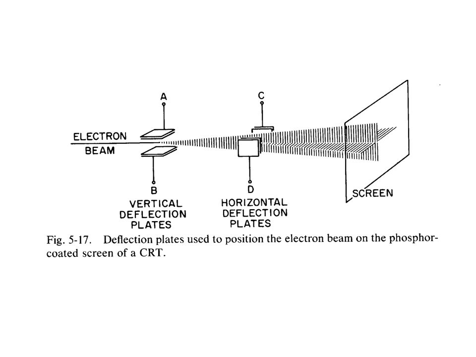
Deflection Plates Deflection plates are used for the positioning the electron beams on the screen: electronstatic or electromagnetic types. Electrostatic type applies voltages to the two sets of plates. Used for small screen with fast speed. Electromagenetic type uses two sets of wire coil. Used for large screen with a slower speed.

26
Phosphor-coated Display Screen Electrons strike the screen (glass coated with phosphorescent materials) and release phosphorescent light. Persistence time: the lifetime of the light emission from the phosphor. Persistence scope: long persistence time up to a few minutes. Composed of storage mesh and flood gun etc. Used as visual monitor for patient positioning with the gamma camera.

27
Focus and Brightness Control Second anode in the CRT controls the focus. It is a potentiometer that varies the potential applied to the anode. The control grid controls the brightness or electron intensity. Increasing the voltage (negative) decreases the intensity
 decreases the intensity.")
28
Colour Cathode Ray Tube Three electron guns produce different electron beams onto arrays of individual phosphors which in turn, produce three colours, red, green and blue. A total of 64 colours can be produced by mixing the three colours for human eyes.

30
Oscilloscopes Oscilloscope is composed of a CRT, a signal amplifier and a time-sweep generator. It is used for displaying signal amplitude or frequency as a function of time. The signal amplifier is used to amplify the small signals to be displayed which is connected to the vertical deflection plates. The sweep signal is applied to horizontal deflection plates which sweeps the electron across the screen at a constant speed and is repeated. Often used in cardiac studies for nuclear medicine

31
Television or Computer Monitors A CRT tube with the two deflection plates controlled by constant frequency time-sweep generators. Electron gun controls the intensity at each point. Active or retrace sweeps: the electron gun is on or off. Most TV monitors use interlacing. The two sets of scan lines are called fields and the two interlaced fields is called frame. Each frame takes 1/30 or 1/25 sec depending on the frequency of the electricity. The resolution depends on the number of lines (65%) for the vertical direction and the changing rate of the brightness during the horizontal sweep.
 for the vertical direction and the changing rate of the brightness during the horizontal sweep..")
Similar presentations


 basics: –Many measurement are made easier by the CRO because it will display not only amplitude,>")


>")

 consists of an ADC, a histogramming memory, and a visual display of the histogram recorded.>")


