Download presentation
Presentation is loading. Please wait.

1
Chapter 11 AC Power Analysis
Circuit Theory Chapter 11 AC Power Analysis Copyright © The McGraw-Hill Companies, Inc. Permission required for reproduction or display.

2
AC Power Analysis Chapter 11
11.1 Instantaneous and Average Power 11.2 Maximum Average Power Transfer 11.3 Effective or RMS Value 11.4 Apparent Power and Power Factor 11.5 Complex Power 11.6 Conservation of AC Power 11.7 Power Factor Correction 11.8 Power Measurement

3
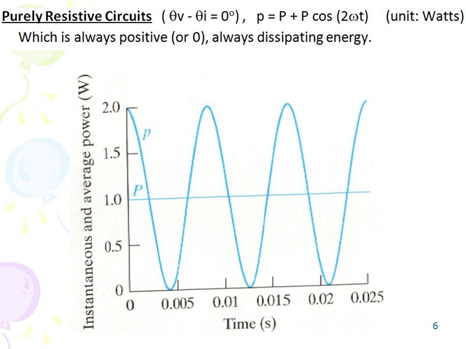
11.1 Instantaneous and Average Power (1)
The instantaneous power, p(t) Constant power Sinusoidal power at 2wt p(t) > 0: power is absorbed by the circuit; p(t) < 0: power is absorbed by the source.
 Constant power. Sinusoidal power at 2wt. p(t) > 0: power is absorbed by the circuit; p(t) < 0: power is absorbed by the source.")
4
Trig Identity Expansion:
Using a common trig identity, p(t) can be expanded as follows: and then regrouped as:
 can be expanded as follows: and then regrouped as:")
5
11.1 Instantaneous and Average Power (2)
The average power, P, is the average of the instantaneous power over one period. P is not time dependent. When θv = θi , it is a purely resistive load case. When θv– θi = ±90o, it is a purely reactive load case. P = 0 means that the circuit absorbs no average power.

7
REACTIVE power instantaneous power

8
instantaneous power REACTIVE power

9
11.1 Instantaneous Average and Reactive Power (3)
Example 1 Calculate the instantaneous power, average power, and reactive power absorbed by a passive linear network if: Answer:

10
11.1 Instantaneous and Average Power (4)
Example 2 A current flows through an impedance Find the average power delivered to the impedance. Answer: 927.2W

11
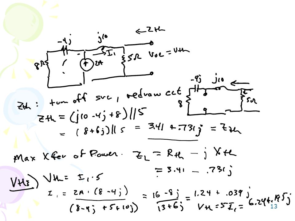
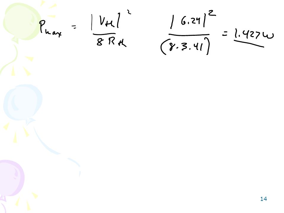
11.2 Maximum Average Power Transfer (1)
The maximum average power can be transferred to the load if XL = –XTH and RL = RTH If the load is purely real, then

12
11.2 Maximum Average Power Transfer (2)
Example 3 For the circuit shown below, find the load impedance ZL that absorbs the maximum average power. Calculate that maximum average power. Answer: – j0.7317W, 1.429W

15
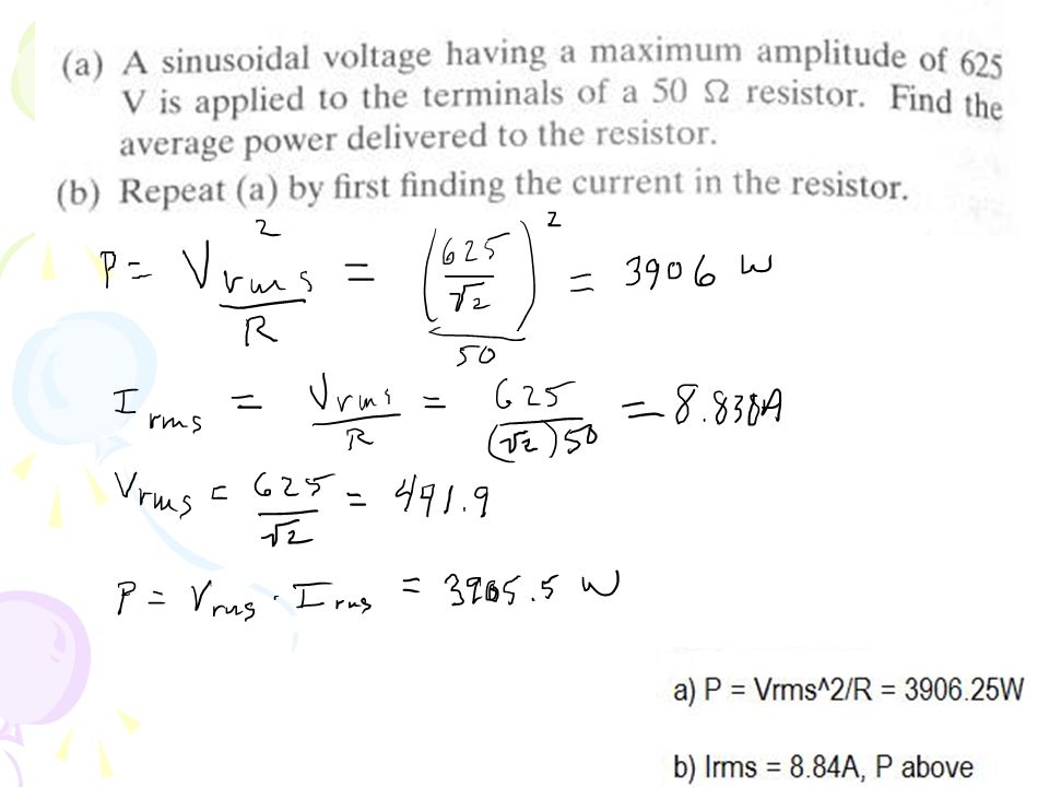
11.3 Effective or RMS Value (1)
The total power dissipated by R is given by: Hence, Ieff is equal to: The rms value is a constant itself which depends on the shape of the function i(t). The effective value of a periodic current is the dc current that delivers the same average power to a resistor as the periodic current.
. The effective value of a periodic current is the dc current that delivers the same average power to a resistor as the periodic current.")
16
11.3 Effective or RMS Value (2)
The rms value of a sinusoid i(t) = Imcos(wt) is given by: The average power can be written in terms of the rms values: Note: If you express amplitude of a phasor source(s) in rms, then all the answer as a result of this phasor source(s) must also be in rms value.
 = Imcos(wt) is given by: The average power can be written in terms of the rms values: Note: If you express amplitude of a phasor source(s) in rms, then all the answer as a result of this phasor source(s) must also be in rms value.")
18
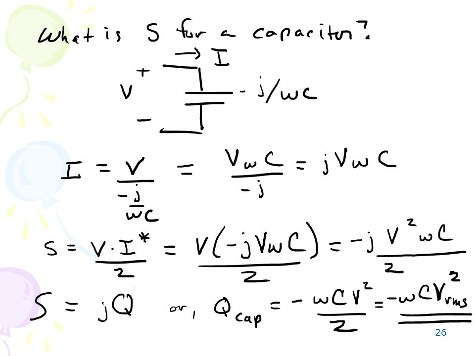
11.5 Complex Power (1) Complex power S is the product of the voltage and the complex conjugate of the current:
 Complex power S is the product of the voltage and the complex conjugate of the current:")
19
11.5 Complex Power (2) S = P j Q P: is the average power in watts delivered to a load and it is the only useful power. Q: is the reactive power exchange between the source and the reactive part of the load. It is measured in VAR. Q = 0 for resistive loads (unity pf). Q < 0 for capacitive loads (leading pf). Q > 0 for inductive loads (lagging pf).
. Q < 0 for capacitive loads (leading pf). Q > 0 for inductive loads (lagging pf).")
20
Units of Power Quantitities
Instantaneous power, p(t) Watts Average power P Watts Reactive power Q VARs Complex power S VA
 Watts. Average power P Watts. Reactive power Q VARs. Complex power S VA.")
21
The Power Triangle

22
Problem 1 Find the average power, the reactive power and the complex power delivered by the voltage source if v = 6 cos (1000t) V P=6.04 mW, Q=6.01mVAR, S=(6.04+j6.01) mVolt-Amp
 mVolt-Amp.")
23
Draw the power triangle from the previous slide. What is power factor
Draw the power triangle from the previous slide. What is power factor? Power factor angle?

24
Load Balancing Most loads tend toward being inductive (lagging pfa)
We can add a capacitor in parallel to increase the power factor towards 1 Reduces overall current needed to drive the load, saves power $

25
Complex Power of multiple components add together
Stotal = S1 + S2 + S3 This lets us change pfa by adding appropriate loads to system.

27
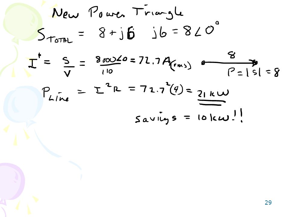
Problem 1 In the circuit, a 110 Vrms load is fed from a transmission line having a impedance of 4 + j1 Ω. The load absorbs an average power of 8 kW at a lagging pf of 0.8. a) Determine the apparent power required to supply the load and the average power lost in the transmission line. b) Compute the value of a capacitor that would correct the power factor to 1 if placed in parallel with the load. Recompute the values in (a) for the load with the corrected power factor. a) |S|=10 kVA, Pline=33.1 kW b) C=0.0013F, Pline'=21.1 kW
 |S|=10 kVA, Pline=33.1 kW. b) C=0.0013F, Pline =21.1 kW.")
30
1)
")
31
2)
")
32
3) How much capacitance should be added in parallel to the load in 2) to increase the power factor to 0.95 ?
 How much capacitance should be added in parallel to the load in 2) to increase the power factor to 0.95")
33
Problem 2 Three 100 Vrms loads are connected in parallel
Problem 2 Three 100 Vrms loads are connected in parallel. Load 1 is a 50 Ω resistor in series with an inductive reactance of 40 Ω. Load 2 absorbs an average power of 500 W at 0.75 lagging power factor. Load 3 absorbs an apparent power of 600 VA at 0.9 lagging power factor. Assume the circuit is operating at 60 Hz. Compute the value of a capacitor that would correct the power factor to 1 if placed in parallel with the loads. 212 uF

Similar presentations


 is the power dissipated on the load resistor. 0 cos 1, dependent on the complex load. ideal power factor: cos =1,>")
 and Reactive.>")


 and industrial loads (such as induction motors)>")


 power Reactive power Complex power Power factor Related educational modules:>")