Download presentation
Presentation is loading. Please wait.

1
Prof. N. Inbaharan

2
Visual Ultrasonic X-ray Thermographic Acoustic Emission Eddy Current Shearography

3
Advanced NDT Solutions Advanced NDT Solutions Industrial Scanners Industrial Scanners Aerospace Inspection Solutions Aerospace Inspection Solutions Stress Corrosion Cracking Solutions Stress Corrosion Cracking Solutions Transportation Solutions Transportation Solutions Corrosion Inspection Solutions Corrosion Inspection Solutions Composite Inspection Solutions Composite Inspection Solutions Tube Inspection Solutions Tube Inspection Solutions Weld Inspection Solutions Weld Inspection Solutions Guided Wave Solutions Guided Wave Solutions Flaw Detectors Flaw Detectors Ultrasonic Flaw Detectors Ultrasonic Flaw Detectors Phased Array Phased Array Guided Wave Guided Wave Eddy Current Products Eddy Current Products Eddy Current Array Products Eddy Current Array Products Bond Testing Bond Testing Transducers and Probes Transducers and Probes Pulser-Receivers Pulser-Receivers Scrap and Recycling XRF Analyzers Scrap and Recycling XRF Analyzers Applications Solutions Key Applications Solutions Key Integrated Inspection Systems Bar Inspection Systems Tube Inspection Systems NDT Systems Instrumentation Thickness Gages 27MG 45MG 38DL PLUS Magna-Mike 8600 35RDC Transducers and Accessories Microscope Solutions Laser Confocal Microscopes Digital Microscopes Semiconductor & Flat Panel Display Inspection Microscopes Upright Metallurgical Microscopes Inverted Metallurgical Microscopes Modular Microscopes Polarizing Microscopes Measuring Microscopes Stereo Microscopes Objective Lenses Digital Cameras Image Analysis Software OEM Microscope Components for Integration Components & Custom Solutions Objective Lenses Optical Microscope Frames Modular Microscope Assemblies Optical Microscope Modules Optical Metrology Laser Confocal Microscopes Digital Microscopes Measuring Microscopes Micro Spectrophotometer Videoscopes, Borescopes Industrial Videoscopes Industrial Fiberscopes Industrial Rigid Borescopes Light Sources Inspection Assist Software Turning Tools XRF Analyzers and XRD Analyzers Handheld XRF Analyzers Portable XRF Analyzers Benchtop XRF Analyzers Process XRF Analyzers Portable XRD Analyzers Benchtop XRD Analyzers Alloys and Metals XRF Analyzers Precious Metals XRF Analyzers

4
Basic principles: – illuminate the test specimen with light – examine the specimen with the eye Used to: – to magnify defects which can not be detected by the naked eye – to assist in the inspection of defects – to permit visual checks of areas not accessible to unaided eye Most widely used of all the nondestructive tests. Simple, easy to apply, quickly carried out and usually low in cost.

5
Magnifying Glass Magnifying Mirror Microscope Borescope – endoscopes or endoprobes Flexible Fiber Optic Borescope – working lengths are normally 60 to 365 cm with diameters from 3 to 12.5 mm Video Imagescope

6
FIBER OPTICS FLEXIBLE BORESCOPE

7
The use of ultrasonic waves to evaluate the condition of a material. Anomalies absorb or deflect the sound waves, which are then detected as changes in the waves. – holes, delaminations, voids – damage, debonds – resin-rich,-poor areas

8
Detector part emitter emitter detector

9
Reflected (pulse-echo)Transmission Mode emitter Emitter – Detector - Transreciver Emitter/Detector Reflector part
Transmission Mode emitter Emitter – Detector - Transreciver Emitter/Detector Reflector part")
11
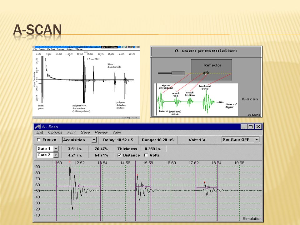
Received pulse amplitude is represented as a displacement along one axis and the travel time of the ultrasonic pulse is represented as a displacement along the other axis. A-scan display are more complex because all reflections are displayed, so signals (back wall, water path) need to be carefully interpretated
 need to be carefully interpretated.")
12
A two-dimensional graphical presentation, in rectangular coordinates, in which the travel time of an ultrasonic pulse is represented as a displacement along one axis, and transducer movement is represented as a displacement along the other axis

13
ENG 4793: Composite Materials and Processes

15
A two-dimensional graphical presentation, in which the discontinuity echoes are displayed in a top view on the test surface. This method is applied to pulse-echo and through transmission techniques. Usually no indication of depth is given unless the complete scan represents the time of flight evaluation (D-scan).
..")
16
ENG 4793: Composite Materials and Processes

17
3D C-scan ENG 4793: Composite Materials and Processes

18
A two-dimensional graphical presentation, in which the time-of-flight values are displayed in a top view on the test surface. This is a modified Cscan in which are amplitudes displayed. ENG 4793: Composite Materials and

20
A two-dimensional graphical presentation, in which the time-of-flight values are displayed in a top view on the test surface. This is a modified C scan in which are amplitudes displayed

21
5-25 MHz typical 0.2- 800 MHz possible Trade-off between frequency (resolution) and depth of penetration – higher frequency, better resolution
 and depth of penetration – higher frequency, better resolution")
23
5-25 MHz typical 0.2- 800 MHz possible Trade-off between frequency (resolution) and depth of penetration – higher frequency, better resolution, lower depth of penetration
 and depth of penetration – higher frequency, better resolution, lower depth of penetration")
24
Film pack or X-ray imaging System Test object X-ray source

25
Film pack or X-ray imaging System Test object Micro focus X-ray source Greatly Enlarged image

27
X-ray source Fluorescent screen Test object TV camera Image processor Monitor scope Intensifier

28
Cooling lines in turbine blade and Porosity in weld

29
Computer mouse IC chip

30
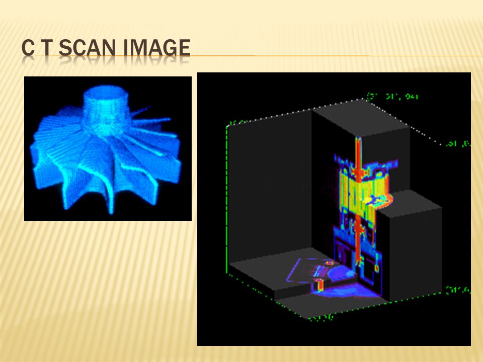
CT produces 3-dimensional images of objects using x-rays. The scanner, made in the shape of a ring, contains an x-ray tube that circles the object. The object in the scanner is bombarded by xrays from various angles and resulting information signals are then processed by a computer, yielding cross sectional slices which then make up images.

34
PC board Aircraft wing

35
Sounds made by a material, structure, or machine in use or under load are heard and analyzed to determine its "state of health". One or more ultrasonic microphones are attached to the object and the sounds are analyzed using computer based instruments. Noises may arise from: – friction (including bearing wear) – crack growth – material changes (such as corrosion)
 – crack growth – material changes (such as corrosion).")
36
Heat Source IR camera part

38
Heat flow in a material is altered by the presence of some types of anomalies. These changes in heat flow cause localized temperature differences in the material. Slow heating of part reveals these anomalies.

39
Heat source Part IR camera Acoustic Emission Principle Sounds made by a material, structure, or machine in use or under load are heard and analyzed to determine its "state of health". One or more ultrasonic microphones are attached to the object and the sounds are analyzed using computer based instruments. Noises may arise from: – friction (including bearing wear) – crack growth – material changes (such as corrosion
 – crack growth – material changes (such as corrosion.")
40
RollerFORMThis new phased array wheel probe facilitates high-quality testing of composite materials (CFRP) offering a viable alternative to immersion techniques. RollerFORM

41
Weld Inspection Solutions full range of weld inspection solutions provides unmatched capabilities for applications that include the location and sizing of hidden cracks, voids, disbonds, and similar discontinuities in welds, forgings, turbines, and other structural components. A wide range of measurement features and application-specific software options are available. The PipeWIZARD is an automated girth weld inspection system using phased array and conventional UT techniques (AUT). Specially designed for in-site weld-to-weld inspection in extreme environments, on-shore and off-shore.
. Specially designed for in-site weld-to-weld inspection in extreme environments, on-shore and off-shore..")
43
Entire structure can be monitored from a few locations. Structure can be tested in use. Continuous monitoring with alarms is possible. Microscopic changes can be detected if sufficient energy is released. Source location is also possible using multiple sensor

Similar presentations


>")

 defects in sound conducting.>")
. Engineering Why use NDT? Components are not destroyed Can test for internal flaws Useful for valuable components.>")
