Download presentation
Presentation is loading. Please wait.

1
Digital Logic Design Week 3
Logic gates (NOT, AND, OR, NAND, NOR, XOR, XNOR) Applications of Binary Codes (MOTIVATION) (ASCII and UNICODE codes, Seven-segment Display Code, Gray code-rotation counter, Error Detection and Correction code)
 Applications of Binary Codes (MOTIVATION) (ASCII and UNICODE codes, Seven-segment Display Code, Gray code-rotation counter, Error Detection and Correction code)")
2
Logic gates Logic gates Fixed-function logic & programmable logic
NOT gate AND gate OR gate NAND gate NOR gate Exclusive-OR (XOR) and exclusive-NOR (XNOR) gates Fixed-function logic & programmable logic
 and exclusive-NOR (XNOR) gates. Fixed-function logic & programmable logic.")
3
Basic logic operations and symbols
True only if all input conditions are true AND OR True only if one or more input conditions are true NOT Indicates the opposite condition X True/false conditions are represented by voltages: HIGH = true LOW = false

4
NOT gate also known as an inverter
performs inversion or complementation HIGH ↔ LOW 1 ↔ 0

5
NOT gate Truth Table A X A truth table shows the output corresponding to each possible input Three equivalent ways to write the NOT condition: X = NOT A X = A’ We’ll use truth tables extensively in the course

6
NOT gate Timing diagram A X A X
Application: A group of inverters can be used to form the 1’s complement of a binary number: Binary number 1’s complement

7
AND gate A B X Produces a HIGH output when all inputs are HIGH; otherwise, the output is LOW

8
AND gate Truth table for a 2-input AND gate
X Truth table for a 2-input AND gate 0 0 0 1 1 0 1 1 1 AND operation is sometimes shown with a dot between the variables, but it may be implied (no dot): AND operation is written as X = A·B or X = AB
: AND operation is written as X = A·B or X = AB.")
9
AND gates have 2 or more inputs
#inputs = n #input combinations (= #rows in truth table) = 2n 2 inputs → 22 = 4 input combinations 3 inputs → 23 = 8 input combinations 4 inputs → 24 = 16 input combinations Write the truth table for a 3-input AND gate
 = 2n. 2 inputs → 22 = 4 input combinations. 3 inputs → 23 = 8 input combinations. 4 inputs → 24 = 16 input combinations. Write the truth table for a 3-input AND gate.")
10
AND gate A B X Timing diagram

11
AND gate

12
OR gate A B X Produces a HIGH output if any input is HIGH; if all inputs are LOW, the output is LOW

13
OR gate Truth table for a 2-input OR gate
X Truth table for a 2-input OR gate 0 0 0 1 1 0 1 1 1 The OR operation is shown with a plus sign (+) between the variables: OR operation is written as X = A + B
 between the variables: OR operation is written as X = A + B.")
14
OR gates have 2 or more inputs
Write the truth table for a 3-input OR gate

15
OR gate

16
NAND gate NAND = NOT-AND Truth table for a 2-input NAND gate
0 0 0 1 1 0 1 1 1 NAND operation is written as or

17
NOR gate NOR = NOT-OR Truth table for a 2-input NOR gate
0 0 0 1 1 0 1 1 1 NOR operation is written as or

18
Alarm to be activated if any door/window is open
Name the mystery gate #1 Alarm to be activated if any door/window is open ?

19
Name the mystery gate #2 ?

20
Name the mystery gate #3 Light turns on if this signal is LOW ???? Want green light ON if both tanks are at least 25% full Level sensor output is HIGH if tank is at least 25% full

21
XOR gate 2-input exclusive-OR (XOR) gate produces a HIGH output if the inputs are at opposite logic levels one HIGH & one LOW Truth table for a 2-input XOR gate 0 0 0 1 1 0 1 1 1 XOR operation is written 3-input XOR defined: extends to N-input XOR

22
XNOR gate A X B 2-input exclusive-NOR (XNOR) gate produces a HIGH output if the inputs are at same logic levels both HIGH, or both LOW Truth table for a 2-input XNOR gate 0 0 0 1 1 0 1 1 1 XNOR operation is written

23
Summary of logic gates

24
1. The binary number 100011010100011011112 expressed in hexadecimal is:
(a) AD46716 (b) 8C46F16 (c) 8D46F16 (d) AE46F16 2. Convert the decimal number to hexadecimal
 AD (b) 8C46F16. (c) 8D46F16. (d) AE46F Convert the decimal number to hexadecimal.")
25
3. Express the decimal number 246910 in binary-coded decimal.
4. A communication system transmits 9-bit blocks of information using an even parity scheme. The following byte of information is to be transmitted: Calculate the value of the parity bit to be attached to this byte.

26
5. For the set of input waveforms shown below, draw the timing diagram showing the output X in relation to the inputs.

27
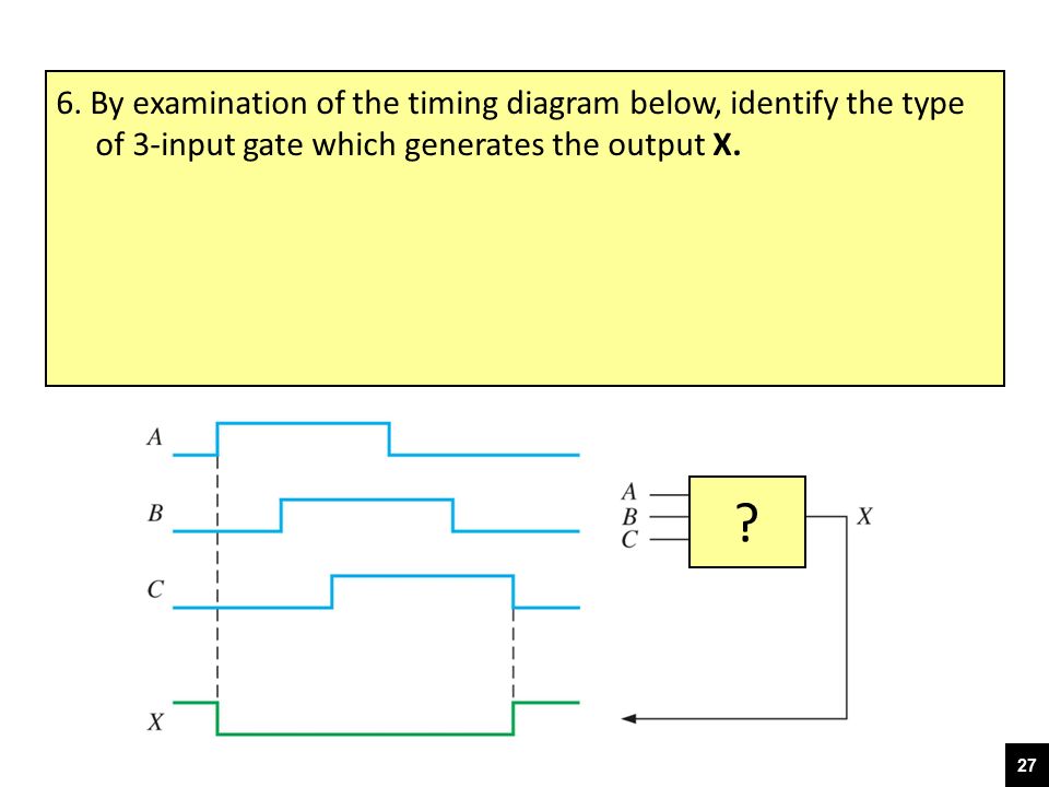
6. By examination of the timing diagram below, identify the type of 3-input gate which generates the output X. ?
28
7. A 2-input gate with inputs A and B generates output X shown in the timing diagram below. The gate is: an OR gate an AND gate a NOR gate a NAND gate A X B

29
9. The truth table for a 2-input NOR gate is:
0 0 0 1 1 0 1 1 1 0 0 0 1 1 0 1 1 1 a. b. 0 0 0 1 1 0 1 1 1 0 0 0 1 1 0 1 1 1 c. d. © 2008 Pearson Education

30
10. Compute the 2’s complement of 011011002
The decimal number is expressed in 8-bit 2’s complement form as:

31
12. Write −3410 as a binary number in 8-bit 2’s complement form
13. Convert each of the following decimal numbers to 8-bit 2’s complement form, and add them: −52 and 25. Check your answer by converting the result back to decimal.

32
14. Convert the hexadecimal number 6B16 to octal (base-8)
15. Perform the following addition of hexadecimal numbers: DF16 + AC16

Similar presentations


8 Digits0, 1, 2, 3, 4, 5, 6, 7 e.g.1623 8 1623 8 3 =5128 2 =648 1 =88 0 =1 The digit.>")


10 Digits0, 1, 2, 3, 4, 5, 6, 7, 8, 9 e.g.7475 10 The magnitude.>")


