Download presentation
Presentation is loading. Please wait.

1
Horizontal Deflection
Done by: Anas Al Jallad

2
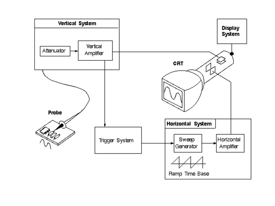
Sweep generator

3
Deflection Systems: To deflect the beam horizontally, an alternating voltage is applied to the horizontal deflecting plates and the spot on the screen horizontally, as shown in Fig. 14-3(b). The electrons will focus at point X2. By changing the polarity of voltage, the beam will focus at point X1. Thus, the horizontal movement is controlled along X1OX2 line.
. The electrons will focus at point X2. By changing the polarity of voltage, the beam will focus at point X1. Thus, the horizontal movement is controlled along X1OX2 line.")
5
Sweep generator (time base) & Horizontal amp.
The horizontal deflecting system consist of a Time Base Generator and an output amplifier. A continuous sweep using a UJT as a time base generator is shown in Figure. Figure show the saw tooth output across the capacitor CT . Rt is used for continuous control of frequency within a range. Ct is changed in steps range changing. The sync pulse enables the sweep frequency to be exactly equal to the input signal frequency.

6
Simple saw-tooth generator & associated waveforms:
The circuit shown in Fig. 14-7(a) is a simple sweep circuit, in which the capacitor C charges through the resistor R. The capacitor discharges periodically through the transistor T1, which causes the waveform shown in Fig. 14-7(b) to appear across the capacitor. The signal voltage, Vi which must be applied to the base of the transistor to turn it ON for short time intervals is also shown in Fig. 14-7(b).
 is a simple sweep circuit, in which the capacitor C charges through the resistor R. The capacitor discharges periodically through the transistor T1, which causes the waveform shown in Fig. 14-7(b) to appear across the capacitor. The signal voltage, Vi which must be applied to the base of the transistor to turn it ON for short time intervals is also shown in Fig. 14-7(b).")
7
Time-base generator using UJT:
The continuous sweep CRO uses the UJT as a time-base generator. When power is first applied to the UJT, it is in the OFF state and CT changes exponentially through RT . The UJT emitter voltage VE rises towards VBB and VE reaches the plate voltage VP. The emitter-to-base diode becomes forward biased and the UJT triggers ON. This provides a low resistance discharge path and the capacitor discharges rapidly. When the emitter voltage VE reaches the minimum value rapidly, the UJT goes OFF. The capacitor recharges and the cycles repeat. To improve the sweep linearity, two separate voltage supplies are used; a low voltage supply for the UJT and a high voltage supply for the RTCT circuit. This circuit is as shown in Fig. 14-7(c). RT is used for continuous control of frequency within a range and CT is varied or changed in steps. They are sometimes known as timing resistor and timing capacitor.
. RT is used for continuous control of frequency within a range and CT is varied or changed in steps. They are sometimes known as. timing resistor and timing capacitor.")
8
Triggered Sweep CRO Using the continuous sweep, when attempting to display voice or music signals, the pattern falls in and out of sync as the frequency and amplitude of the music varies resulting in an unstable display. A triggered sweep can display such signals, and those of short duration. In triggered mode, the input signal is used to generate substantial pulses that trigger the sweep. This ensures that the sweep is always in step with the signal that drives it.

9
Trigger Fault

10
Trigger generation Trigger Sawtooth

11
Positive trigger level
Sawtooth

12
Negative trigger level
Sawtooth

13
Part of the signal: less than one period
Trigger Hold-on time Sawtooth

14
Part of the signal: more than one period
Trigger Sawtooth

Similar presentations
For the fig sketch the output waveform. What is the maximum positive voltage? The maximum negative?>")


>")


 Voltmeter that captures voltage samples & displays them on a screen Voltage.>")


 Deptt. Of EE>")
