Download presentation
Presentation is loading. Please wait.

1
Lecture - 5 Nodal analysis

2
Outline Terms of describing circuits. The Node-Voltage method. The concept of supernode.

3
Terms of describing circuits NameDefinitions NodeA point where two or more circuit elements join Essential nodeA node where three or more circuit elements join PathA trace of adjoining basic elements with no elements included more than once BranchA path that connects two nodes Essential branchA path which connects two essential nodes without passing through an essential node LoopA path whose last node is the same as the starting node meshA loop that does not enclose any other loops planar circuitA circuit that can be drawn on a plane with no crossing branches

4
Example 1 For the circuit in the figure, identify a) all nodes. b) all essential nodes. c) all branches. d) all essential branches. e) all meshes. f) two paths that are not loops or essential branches. g) two loops that are not meshes.
 all essential nodes. c) all branches. d) all essential branches. e) all meshes. f) two paths that are not loops or essential branches. g) two loops that are not meshes..")
5
Example 1 a)The nodes are a, b, c, d, e, f, and g. b) The essential nodes are b, c, e, and g. c) The branches are v 1, v 2, R 1, R 2, R 3, R 4, R 5, R 6, R 7 and I. d) The essential branches are: v 1 – R 1, R 2 – R 3, v 2 – R 4, R 5, R 6, R 7 and I
 The essential nodes are b, c, e, and g. c) The branches are v 1, v 2, R 1, R 2, R 3, R 4, R 5, R 6, R 7 and I. d) The essential branches are: v 1 – R 1, R 2 – R 3, v 2 – R 4, R 5, R 6, R 7 and I.")
6
Example 1 e) The meshes are: v 1 – R 1 – R 5 – R 3 – R 2, v 2 –R 2 – R 3 – R 6 –R 4, R 5 – R 7 – R 6 and R 7 –I f) The two paths that are not loops or essential branches are R 1 – R 5 – R 6 and v 2 - R 2, because they do not have the same starting and ending nodes), nor are they an essential branch (because they do not connect two essential nodes). g) The two loops that are not meshes are v 1 — R 1 — R 5 – R 6 - R 4 - v 2 and I — R 5 —R 6, because there are two loops within them.
 The two loops that are not meshes are v 1 — R 1 — R 5 – R 6 - R 4 - v 2 and I — R 5 —R 6, because there are two loops within them..")
7
The Node-Voltage method Steps to determine Node Voltages: 1.Select a node as the reference node. Assign voltage v 1, v 2, …v n-1 to the remaining n-1 nodes. The voltages are referenced with respect to the reference node. 2.Apply KCL to each of the n-1 non-reference nodes. 3.Use Ohm’s law to express the branch currents in terms of node voltages. 4.Solve the resulting simultaneous equations to obtain the unknown node voltages.

8
Example 2 a) Use the node-voltage method of circuit analysis to find the branch currents i a, i b, and i c in the circuit shown. b) Find the power associated with each source, and state whether the source is delivering or absorbing power.
 Find the power associated with each source, and state whether the source is delivering or absorbing power..")
9
Example 2 a) There are two essential nodes; thus we need to write a single node voltage expression. We select the lower node as the reference node and define the unknown node voltage as v 1. Summing the currents away from node 1 generates the node-voltage equation: Solving for v 1 gives v 1 =40V Hence b) P 50V = -50i a = -100 W (delivering). P 3A = -3v 1 = -3(40) = -120 W (delivering).
 P 50V = -50i a = -100 W (delivering). P 3A = -3v 1 = -3(40) = -120 W (delivering)..")
10
Example 3 Use the node-voltage method to find the power dissipated in the 5Ω resistor in the circuit shown. -------------------------------------------------------- We begin by noting that the circuit has three essential nodes. Hence we need two node-voltage equations to describe the circuit. Four branches terminate on the lower node, so we select it as the reference node. The two unknown node voltages are defined on the circuit. Summing the currents away from node 1 generates the equation.

11
Example 3 Summing the currents away from node 2 yields As written, these two node-voltage equations contain three unknowns, namely, v1, v2, and i Φ. To eliminate i Φ we must express this controlling current in terms of the node voltages

12
Example 3 Substituting this relationship into the node 2 equation simplifies the two node-voltage equations to Solving for v 1 and v 2 gives v 1 =16V and v 2 = 10V Then

13
The Concept of a Supernode A supernode is formed by enclosing a (dependent or independent) voltage source connected between two non-reference nodes and any elements connected in parallel with it. The required two equations for regulating the two non-reference node voltages are obtained by the KCL of the super node and the relationship of node voltages due to the voltage source

14
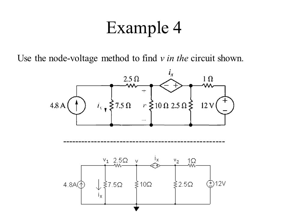
Example 4 Use the node-voltage method to find v in the circuit shown. ---------------------------------------------------
15
Example 4 Note that the dependent voltage source and the node voltages v and v 2 form a supernode. The v 1 node voltage equation is The supernode equation is The constraint equation due to the dependent source is

16
Example 4 The constraint equation due to the supernode is: Place this set of equations in standard form: Solving this set of equations gives v 1 = 15 V, v 2 = 10 V, i x = 2 A, and v = 8 V.

17
Summary Those terms are node, essential node, path, branch, essential branch, mesh, and planar circuit. The node-voltage method works with both planar and non-planar circuits. A reference node is chosen from among the essential nodes. Voltage variables are assigned at the remaining essential nodes, and Kirchhoff s current law is used to write one equation per voltage variable. The number of equations is n e — 1, where n e is the number of essential nodes

Similar presentations


: Circuits I Spring 2014 1 April 10, 2014.>")


