Download presentation
Presentation is loading. Please wait.

1
Grating reconstruction forward modeling part Mark van Kraaij CASA PhD-day Tuesday 13 November 2007

2
Jamie and Adam explain Moore’s Law Source: www.intel.com

3
Wafer: 300 mm From wafer to grating Intel Core2 Duo: 13.6 mm 1 m1 m Grating: 500 nm pitch, 70 nm linewidth Source: www.intel.com

4
1.Project description 2.Forward modeling part –2.1: Diffraction model –2.2: Error analysis 3.Improvements –3.1: Finite differences –3.2: Adaptive spatial resolution 1.Project description 2.Forward modeling part –2.1: Diffraction model –2.2: Error analysis 3.Improvements –3.1: Finite differences –3.2: Adaptive spatial resolution Outline

5
Microscope objective Xenon light source Wafer, , I ASML Tool Library of modeled data Filter CCD, , Library search++ Reconstructed profile 1. Project description A tool is needed that can measure profile information for CD and Overlay metrology

6
Outline 1.Project description 2.Forward modeling part –2.1: Diffraction model –2.2: Error analysis 3.Improvements –3.1: Finite differences –3.2: Adaptive spatial resolution

7
Assumptions (EM field): –Electromagnetic field quantities are time-harmonic –Incident field is an arbitrary (linearly) polarized monochromatic plane wave Assumptions (grating): –Media are isotropic, stationary → linear constitutive relations –Grating is infinitely periodic and approximated with a layered structure Assumptions (grating): –Media are isotropic, stationary → linear constitutive relations –Grating is infinitely periodic 2.1 Diffraction model: Assumptions SEM: finite periodic grating Model: infinite periodic grating
: –Electromagnetic field quantities are time-harmonic –Incident field is an arbitrary (linearly) polarized monochromatic plane wave Assumptions (grating): –Media are isotropic, stationary → linear constitutive relations –Grating is infinitely periodic and approximated with a layered structure Assumptions (grating): –Media are isotropic, stationary → linear constitutive relations –Grating is infinitely periodic 2.1 Diffraction model: Assumptions SEM: finite periodic grating Model: infinite periodic grating")
8
Rayleigh radiation condition Pseudo-periodic boundary condition Continuity boundary condition 2.1 Diffraction model: Equations and bc’s x z TM polarization: TE polarization:

9
Expand electric field in top and bottom layer in eigenfunctions (pseudo-periodic Fourier series) Expand electric field and permittivity function in intermediate grating layers also in (pseudo-periodic) Fourier series 2.1 Diffraction model: Discretization and truncation Truncate series and solve 2 nd order ODE in grating layers
 Expand electric field and permittivity function in intermediate grating layers also in (pseudo-periodic) Fourier series 2.1 Diffraction model: Discretization and truncation Truncate series and solve 2 nd order ODE in grating layers")
10
2.1 Diffraction model: Final system of equations Use continuity boundary conditions at layer interfaces Solve system with stable condensation algorithm Fundamental solutions consist of –N growing components –N decreasing components Interface between layer i and i+1 Completely separated boundary conditions

11
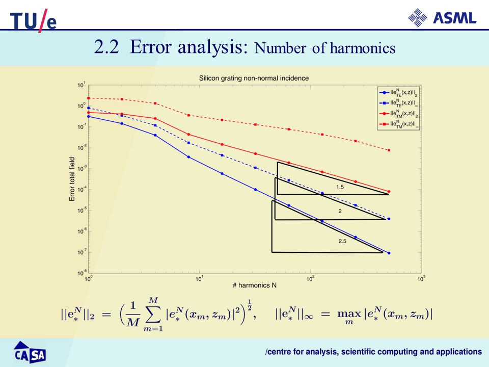
2.2 Error analysis: Number of harmonics

13
.

14
Outline 1.Project description 2.Forward modeling part –2.1: Diffraction model –2.2: Error analysis 3.Improvements –3.1: Finite differences –3.2: Adaptive spatial resolution

15
Bloch 3. Improvements Separation of variables gives with pseudo-periodic bc’s, with continuity bc’s at layer interface, where Eigenvalues are related to the roots of Eigenfunctions typically look like

16
Single domain approach 3.1 Improvements: Finite differences Discretize equation on most interior points using central differences Discretize equation on some interior points using modified central differences Discretize equation on interior points using central differences Discretize boundary condition on boundary points using one-sided differences x0x0 x1x1 x M-1 xMxM x N-1 xNxN Goal: Improve accuracy by replacing Fourier with finite difference discretization (transitions modeled better) Partitioned domain approach x0x0 x1x1 x M-1 x M,a/b x M+ 1 x N-1 xNxN
 Partitioned domain approach x0x0 x1x1 x M-1 x M,a/b x M+ 1 x N-1 xNxN")
17
Single domain approach Compute eigenvalues, scheme overall O(h 2 ): Partitioned domain approach Compute eigenvalues, scheme overall O(h 2 ): Partitioned domain approach Compute eigenvalues, scheme overall O(h): Eigenvalues computed using standard techniques for full matrices. At the moment not able to exploit sparse structure of matrix… Partitioned domain approachSingle domain approach 3.1 Improvements: Finite differences

18
By a change of variable in each layer the spatial resolution is increased around the discontinuities Properties: –The electric field and permittivity in each layer i are expanded in a layer specific basis which depends on the locations of the transition points –The basis functions in each layer are projected on the plane wave basis when connecting layers 3.2 Improvements: Adaptive spatial resolution

19
Question1: Should all eigenvalues be used? 500 nm silicon block, non-normal incidence, 0 = =1mu, (TE, N=10) Exact eigenvalues (Bloch) -1.349076641333984e+001 -1.135076524908338e+001 -7.892853673610714e+000 -3.454082776318814e+000 1.276327724136246e-001 7.878383953399616e-001 4.951776353671870e+000 6.064364267444717e+000 1.286665389409586e+001 1.347902372017457e+001 2.288512237078319e+001 … propagating evanescent 500 nm silicon block, non-normal incidence, 0 = =1mu, (TM, N=10) Exact eigenvalues (Bloch) -1.323802014939081e+001 -1.032763462047682e+001 -5.576329792050528e+000 -1.266781396948507e+000 1.154532768840351e-001 1.029193134524742e+000 3.848084904617279e+000 7.334522367194479e+000 1.139286665954855e+001 1.467711974044035e+001 2.201015238581615e+001 …
 Exact eigenvalues (Bloch) e e e e e e e e e e e+001 … propagating evanescent 500 nm silicon block, non-normal incidence, 0 = =1mu, (TM, N=10) Exact eigenvalues (Bloch) e e e e e e e e e e e+001 ….")
20
3.2 Improvements: Adaptive spatial resolution Question2: How to compute projection matrix ? Numerical quadrature difficult due to high frequencies FFT might be possible since integral can be seen as computing a Fourier coefficient Rewrite into standard Bessel related integrals::

21
Summary Stability RCWA understood and linked to standard techniques Gaining insights in error estimates Finite differences alternative for Fourier but not yet competitive ASR another alternative for standard Fourier but still work to be done on –choosing optimal stretching parameter –implementing special functions

23
2.2 Error analysis: Number of harmonics

25
.

26
Special functions Anger function: Properties: –When integer: regular Bessel function –When non-integer and small z: Power series expansion with Lommel functions large z: Asymptotic expansions with second kind Lommel functions and regular cylindrical Bessel functions –Recurrence relation for 3.2 Improvements: Adaptive spatial resolution

27
Special functions Weber function: Properties: –When integer: series expansion with Gamma and Struve functions –When non-integer and small z: Power series expansion with Lommel functions large z: Asymptotic expansions with second kind Lommel functions and irregular cylindrical Bessel functions –Recurrence relation for 3.2 Improvements: Adaptive spatial resolution

28
Old results: ASR improves convergence of diffraction efficiencies in TE polarization, but TM fails… Diffraction efficiency 0 th order NOldNew 50.11647460.1406958 100.10112640.1317428 150.12085120.1317091 200.12694840.1317092 250.12917390.1317092 300.13022580.1317092 350.13076000.1317092 400.13107020.1317092 2000.1317039 Diffraction efficiency 1 st order NOldNew 50.85281820.7286252 100.76226940.7342224 150.74409380.7342789 200.73857290.7342789 250.73655540.7342788 300.73561160.7342788 350.73512960.7342788 400.73485210.7342788 2000.7342836 30 0 R0R0 R1R1 = m = m n = 0.22-6.71i d = 1 m 3.2 Improvements: Adaptive spatial resolution

29
Jamie and Adam explain Moore’s Law Source: www.intel.com

Similar presentations


>")


