Download presentation
Presentation is loading. Please wait.

1
Team Leader: Christopher Morehouse (ME) Team Members: Julie Maier (ME) Caroline Bills (ME) Ted Zachwieja (ME) Faculty Advisor: Ed Hanzlik Customer: Dr. Alan Nye P11221-Noise Reduction for Internal Combustion Engines

2
Improve & challenge the proposed designs Obtain assistance where needed from attendees Purpose of Review

3
Agenda Project Overview Scope Overview Customers and Users Project Flow Chart Project Plan & Risks Engine Test Set-up Engine Test Data Design Concepts ImagineRIT Demo Set-up Expected Outcomes – Near Future Plans Questions & Discussions

4
PROJECT OVERVIEW

5
1. Investigate physics of sound generation & transmission 2. Identify & locate major noise contributors in an ICE 3. Analyze & model noise generation of an ICE 4. Create design(s) for noise reduction mechanism 5. Provide sufficient background to EE team for active noise cancellation system 6. Produce simple engine test stand for proof of concept (ICE = Internal Combustion Engine) Revised Project Scope
 for noise reduction mechanism 5. Provide sufficient background to EE team for active noise cancellation system 6. Produce simple engine test stand for proof of concept (ICE = Internal Combustion Engine) Revised Project Scope.")
6
Engine Sound Model ◦ Frequency response for varying RPM ◦ For EE team ANC System Constraints ◦ EE team will follow Develop Engine Test Stand Develop prototype noise reduction mechanical systems Create demonstrator for ImagineRIT Project Deliverables

7
Project Breakdown

8
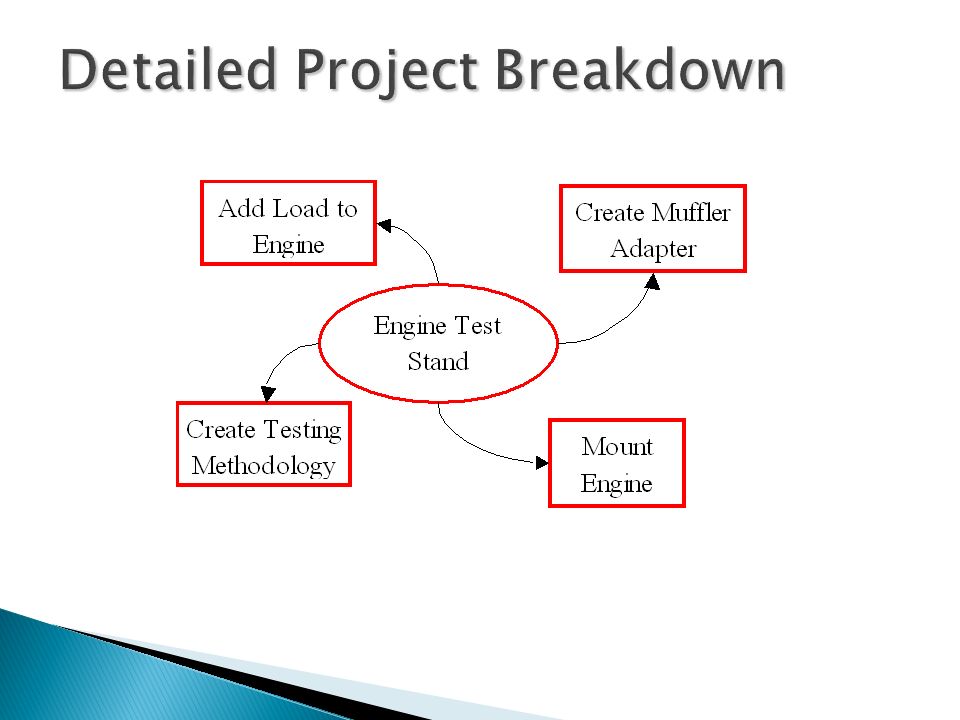
Detailed Project Breakdown

10
Customer Needs

11
Engineering Specifications

12
Most Important Engineering Specs: ES 1- Reduce noise level ES 9 - Internal Exhaust Components Survivable Temp ES 10 - Internal Exhaust Components Survivable Pressure ES 15 - Measure sound level according to SAE specs Relationship Diagram

13
The Plan (MSD I)
")
15
The Plan (MSD II)
")
16
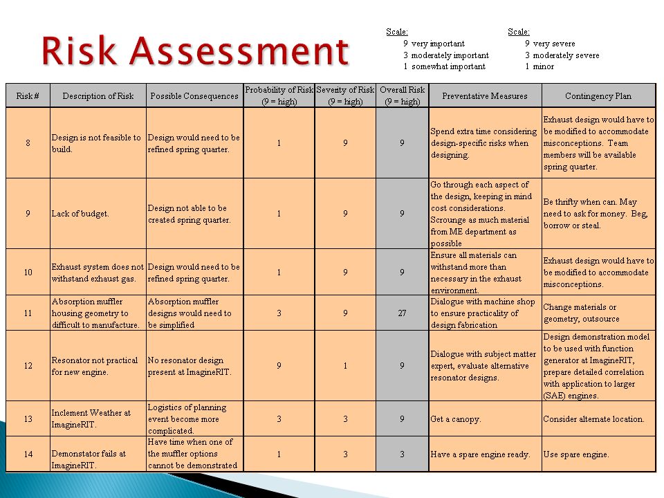
Risk Assessment

18
Most Important Risks

19
ENGINE TEST RIG

20
Schematic

21
Current Engine Set-up

22
ENGINE CHARACTERIZATION

23
Sound Testing Procedure TOP VIEWFRONT VIEW Exit

24
Formula car Microphone Muffler

25
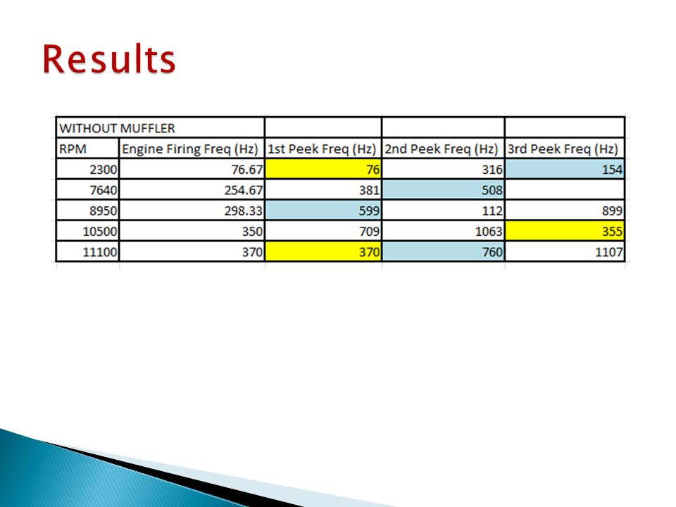
Sound Recording Waveform – Without Muffler Frequency Analysis – Without Muffler (at 10,200 RPM)
")
28
Engine Firing Freq: 53.3

31
Preliminary Lawnmower Data Test #1: ◦ Cart stationary, Decimeter rotated ◦ Exhaust pointing into alley towards dumpster

32
Preliminary Lawnmower Data Test #2: ◦ Cart & Decimeter rotated

33
Engine 101.5 96.5 95 91.5 103 99 98 92 100.5 95.5 93 90 98 95 93.5 91 98.5 96 94 89 102 98 95 93 99 95 96 91 101.5 97 94.5 93 20” 40” 60” 120” Sound Pressure Level Map: Top View, Horizontal Plane

34
NOISE ABATEMENT DESIGN OPTIONS

35
Glass Pack ◦ Low flow restriction ◦ Low noise attenuation Current Formula Car Muffler Design

36
Unpacked Concentric Tube Resonator Packed Concentric Tube: ◦ Metal Foam ◦ Lava Rock/Rockwool and Stainless Steel Wool Variable Length Resonator - Single Pass ANC (End Cap Silencer, Multiple Exhaust Pipes) Previous Design Option List
 Previous Design Option List")
37
Current Formula ◦ Honda 600cc ◦ 85hp ◦ 4-Cylinder ◦ 4-Stroke Lawnmower ◦ Briggs & Stratton ◦ 5.5hp ◦ 1-Cylinder ◦ 4-Stroke Engine Comparison

38
Single-pass Concentric Tube Resonator

39
Formula SAE Lawnmower rpmf (Hz)λ (m)1/2 λ (m)1/2 λ (ft) 5004.1781.6740.84124.47 10008.3340.8420.4262.23 150012.5027.2213.6141.49 200016.6720.4210.2131.12 250020.8316.338.1724.89 300025.0013.616.8120.74 350029.1711.675.8317.78 rpmf (Hz)λ (m)1/2 λ (m)1/2 λ (ft)1/2 λ (in) 5001720.4210.2131.12373.4 10003310.215.1015.56186.7 1500506.813.4010.37124.5 2000675.102.557.7893.4 2500834.082.046.2274.7 30001003.401.705.1962.2 35001172.921.464.4553.3 40001332.551.283.8946.7 45001502.271.133.4641.5 50001672.041.023.1137.3 55001831.860.932.8333.9 60002001.700.852.5931.1 65002171.570.792.3928.7 70002331.460.732.2226.7 75002501.360.682.0724.9 80002671.280.641.9423.3 85002831.200.601.8322.0 90003001.130.571.7320.7 95003171.070.541.6419.7 100003331.020.511.5618.7 105003500.970.491.4817.8 110003670.930.461.4117.0 115003830.890.441.3516.2 120004000.850.431.3015.6 Conclusion : ◦ Resonator not feasible for lawnmower engine Resonator Optimal Length f = (RPM) * n / 120 n = number of cylinders λ = c / f c = speed of sound in air (340.3 m/s)
λ (m)1/2 λ (m)1/2 λ (ft) rpmf (Hz)λ (m)1/2 λ (m)1/2 λ (ft)1/2 λ (in) Conclusion : ◦ Resonator not feasible for lawnmower engine Resonator Optimal Length f = (RPM) * n / 120 n = number of cylinders λ = c / f c = speed of sound in air (340.3 m/s)")
40
Helmholtz Resonator f = Frequency c = Speed of Sound in Air L = Length of Neck A = Cross-Sectional Area of Neck V = Volume of Chamber

41
Narrow frequency band Active option too large Will not pursue

42
Absorption Muffler Design Three shapes, each: ◦ Length = 12 in ◦ ID = 1in ◦ Thickness = 2in Four packing materials Test for optimization of sound absorption

43
Design I

44
Design II

45
Design III

46
Packing Materials Metal Foam Fiberglass Stainless Steel Wool ◦ Fine ◦ Medium ◦ Coarse Rockwool

47
Casing/Inner Tube Packing Materials: ◦ Stainless Steel Casing ◦ Stainless Steel Inner Tube Perforated Metal Sheet Metal Metal Foam: ◦ Aluminum Casing

48
Absorption Mufflers: Bill of Materials

51
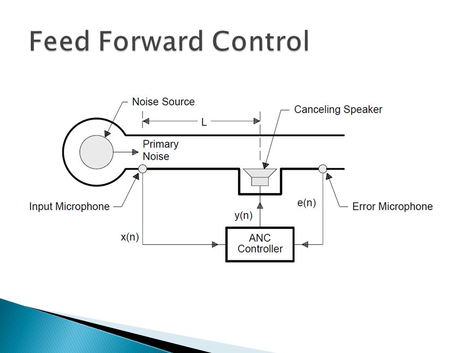
http://focus.ti.com.cn/cn/lit/an/spra042/spra042.pdf

52
Engine Dipole Box Parallel Pipe from Speaker

57
Create Engine Test Stand (not cart) Create posters Obtain actual car mufflers & dissect Get both engines ready (fuel & oil) Get TV & set it up
 Create posters Obtain actual car mufflers & dissect Get both engines ready (fuel & oil) Get TV & set it up")
58
Engine fails during demonstration ◦ Have backup engines Weather ◦ Find alternate location (Machine Shop?) ◦ Get another canopy
 ◦ Get another canopy")
59
1 – 10’ x 10’ Canopy 2 – Tables (approx. 5’ x 2’) 1 – Table (can be drilled into) 4 – Chairs 1 – TV Screen & accompanying cables 2 – 1hp Briggs & Stratton Lawnmower engines 1 – Laptop 1 – Microphone 1 – Decimeter 1 – Handheld Tachometer
 1 – Table (can be drilled into) 4 – Chairs 1 – TV Screen & accompanying cables 2 – 1hp Briggs & Stratton Lawnmower engines 1 – Laptop 1 – Microphone 1 – Decimeter 1 – Handheld Tachometer.")
60
Action ItemGoalNo Later Than Design Commitment Oct. 15 Data Collection (CB)Oct. 14Oct. 21 Engine Model (CM)Oct. 18Oct. 25 Design Resonator (JM)Oct. 22Oct. 25 Detailed BOM & Budget (CB)Oct. 29 Detailed ANC Component Requirements (TZ)Oct. 22Oct. 29 Detailed ANC Layout & Mounting Schematic (TZ)Oct. 29Nov. 1 Critical Action Items
Oct. 14Oct. 21 Engine Model (CM)Oct. 18Oct. 25 Design Resonator (JM)Oct. 22Oct. 25 Detailed BOM & Budget (CB)Oct. 29 Detailed ANC Component Requirements (TZ)Oct. 22Oct. 29 Detailed ANC Layout & Mounting Schematic (TZ)Oct. 29Nov. 1 Critical Action Items.")
61
Action ItemGoal No Later Than Report to EE team 11/711/15 Create Complete BOM11/1211/15 Characterize Lawnmower11/911/15 Finalize Absorption11/911/15 Resonator Demonstrator11/1211/15 Data Analysis SAE car11/1211/15 Order Materials Absorption11/19 New Critical Action Items

62
Sources www.rit.edu/imagine Experimental Investigation of Active Noise Controller for Internal Combustion Engine Exhaust System by: Jian-Da Wu et al. Industrial Noise Control: Fundamentals and Applications by Lewis H. Bell www.crownaudio.com Dr. Zheji Lui (Dresser-Rand)
.")
Similar presentations


 CLEPA presentations supporting justifications of informal documents GRB-47-2.>")

- Team Lead Brad Fiedler (EE) Greg Wodzicki (EE) Chris VanWagenen (EE) George Slack- Faculty Guide P11227- ACTIVE NOISE CANCELLATION.>")


