Download presentation
Presentation is loading. Please wait.

1
Unit 10.2 Timer Examples

2
Example – Music Generation Channel 6 – Set up as a timer Output to Generate Square Waves Channel 4 – Set up as a timer Output to control the length of each tone. Free-running counter will have a time resolution of 1 Microsecond

3
Music Generation 1 Sec Output 4 1 Sec Output 4 1 Sec Output 4 1 Sec Output 4 Output 6 Frequency F1 Output 6 Frequency F2 Output 6 Frequency F3 Output 6 Frequency F4

4
Details of implementation Channel 4 is used to generate an Interrupt every 50 milliseconds –20 interrupts = 1 second –Select a new frequency for Channel 6’s output at end of each 1 second interval Prescale value of 2 is used to provide 1 MHZ clock to free- running counter - Unit clock period is therefore 1 microsecond

5
Frequency of Notes Note Frequency Period (usec) C2623816.8 C#2723676.5 D2943401.4 D#3113215.4 E3303030.3 F3492865.3 F#3692710.0 G3922551.0 G#4152409.6 A4402272.7 A#4662145.9 B4952020.2
 C C# D D# E F F# G G# A A# B")
6
Software Initialization ---- // forward references to interrupt service routines void oc6_isr(void) __attribute__ ((interrupt)); // IC6 Interrupt void oc4_isr(void) __attribute__ ((interurpt)): // IC4 interrupt ---- // global variables – period of each note unsigned int freq[12] = 3817, 3677, 3401, 3215, 3030, 2865, 2710,2551, 2410, 2273, 2146, 2020; // global variable - song unsigned char music[13] = 0,1,2,3,4,5,6,7,8,9,10,11,0xFF; //index of notes in song--12 notes plus end flag ---- unsigned int tp4 = 50000; //50 milliseconds unsigned int tp6 = 3817/2; // half period for C note unsigned idx1=0, idx2=0; ----
![Software Initialization ---- // forward references to interrupt service routines void oc6_isr(void) __attribute__ ((interrupt)); // IC6 Interrupt void oc4_isr(void) __attribute__ ((interurpt)): // IC4 interrupt ---- // global variables – period of each note unsigned int freq[12] = 3817, 3677, 3401, 3215, 3030, 2865, 2710,2551, 2410, 2273, 2146, 2020; // global variable - song unsigned char music[13] = 0,1,2,3,4,5,6,7,8,9,10,11,0xFF; //index of notes in song--12 notes plus end flag ---- unsigned int tp4 = 50000; //50 milliseconds unsigned int tp6 = 3817/2; // half period for C note unsigned idx1=0, idx2=0; ----](http://images.slideplayer.com/24/7378745/slides/slide_6.jpg "Software Initialization ---- // forward references to interrupt service routines void oc6_isr(void) __attribute__ ((interrupt)); // IC6 Interrupt void oc4_isr(void) __attribute__ ((interurpt)): // IC4 interrupt ---- // global variables – period of each note unsigned int freq[12] = 3817, 3677, 3401, 3215, 3030, 2865, 2710,2551, 2410, 2273, 2146, 2020; // global variable - song unsigned char music[13] = 0,1,2,3,4,5,6,7,8,9,10,11,0xFF; //index of notes in song--12 notes plus end flag ---- unsigned int tp4 = 50000; //50 milliseconds unsigned int tp6 = 3817/2; // half period for C note unsigned idx1=0, idx2=0; ----")
7
Main Program int main() { --- TSCR2 = 0x01; // 1 usec resolution with TNCT,using // prescale factor of 2 on internal 2 MHz clock // No TOF Interrupt ---- // initialize Channel 6 for generating square wave ---- // initialize Channel 4 for control of interval length for each note --- ENABLE(); // enable interrupts ---- }
 { --- TSCR2 = 0x01; // 1 usec resolution with TNCT,using // prescale factor of 2 on internal 2 MHz clock // No TOF Interrupt ---- // initialize Channel 6 for generating square wave ---- // initialize Channel 4 for control of interval length for each note --- ENABLE(); // enable interrupts ---- }")
8
Initialize Channel 6 /* Initialize Output Compare Channel 6 Complement on Each Compare Timer has been initialized */ TIOS = TIOS | 0x40: // Set Channel 6 to Output Compare – Bit 6 // TIOS = x1xx xxxx TCTL1 = (TCTL1&0xCF) | 0x10; // Toggle Output Line 6 (square wave) // TCTL1 = xx01 xxxx TFLG1 = 0x40; // Clear Channel 6 Flag TC6 = TCNT + tp6; // Complement in tp6 Seconds Set earlier to be half period of C Note
 | 0x10; // Toggle Output Line 6 (square wave) // TCTL1 = xx01 xxxx TFLG1 = 0x40; // Clear Channel 6 Flag TC6 = TCNT + tp6; // Complement in tp6 Seconds Set earlier to be half period of C Note")
9
Using Interrupts for Channel 6 Task SETVECT(0xFFE2, oc6_isr); // set interrupt vector TIE = TIE | 0x40; // Enable Channel 6 Interrupt ---- void oc6_isr(void) {// Period of square wave is 2*tp6 TC6 = TC6 + tp6; // Next interrupt set up for tp6 from now TFLG1 = 0x40; // Clear Channel 6 Flag }
; // set interrupt vector TIE = TIE | 0x40; // Enable Channel 6 Interrupt ---- void oc6_isr(void) {// Period of square wave is 2*tp6 TC6 = TC6 + tp6; // Next interrupt set up for tp6 from now TFLG1 = 0x40; // Clear Channel 6 Flag }")
10
Initialize Channel 4 /* Initialize Output Compare Channel 4 Complement on Each Compare Timer has been initialized */ TIOS = TIOS | 0x10: // Set Channel 4 to Output Compare – Bit 4 // TIOS = xxx1 xxxx TCTL1 = (TCTL1&0xFC) | 0x01; // Toggle Output Line 4 // TCTL1 = xxxx xx01 – Toggle Pin 4 TFLG1 = 0x10; // Clear Channel 4 Flag TC4 = TCNT + tp4; // Complement in tp4 Seconds // tp4 = 50 000 microseconds
 | 0x01; // Toggle Output Line 4 // TCTL1 = xxxx xx01 – Toggle Pin 4 TFLG1 = 0x10; // Clear Channel 4 Flag TC4 = TCNT + tp4; // Complement in tp4 Seconds // tp4 = microseconds")
11
Using Interrupts for Channel 4 Task SETVECT(0xFFE6, oc4_isr); // set interrupt vector TIE = TIE | 0x10; // Enable Channel 4 Interrupt ---- ---- initially set to 50000 void oc4_isr(void) {TC4 = TC4 + tp4; // Complement T from now and generate // interrupts 20 times per second TFLG1 = 0x10; // Clear Channel 4 Flag idx0++; // Count Channel 4 interrupts up to 20 if(idx0>20) initially set to 0 { // 1 second has elapsed idx0=0; idx1++; //bump up index to next note if (music[idx1]==0xFF)idx1=0; tp6 = freq[music[idx1]]/2; // select period of next note }
![Using Interrupts for Channel 4 Task SETVECT(0xFFE6, oc4_isr); // set interrupt vector TIE = TIE | 0x10; // Enable Channel 4 Interrupt initially set to void oc4_isr(void) {TC4 = TC4 + tp4; // Complement T from now and generate // interrupts 20 times per second TFLG1 = 0x10; // Clear Channel 4 Flag idx0++; // Count Channel 4 interrupts up to 20 if(idx0>20) initially set to 0 { // 1 second has elapsed idx0=0; idx1++; //bump up index to next note if (music[idx1]==0xFF)idx1=0; tp6 = freq[music[idx1]]/2; // select period of next note }](http://images.slideplayer.com/24/7378745/slides/slide_11.jpg "Using Interrupts for Channel 4 Task SETVECT(0xFFE6, oc4_isr); // set interrupt vector TIE = TIE | 0x10; // Enable Channel 4 Interrupt initially set to void oc4_isr(void) {TC4 = TC4 + tp4; // Complement T from now and generate // interrupts 20 times per second TFLG1 = 0x10; // Clear Channel 4 Flag idx0++; // Count Channel 4 interrupts up to 20 if(idx0>20) initially set to 0 { // 1 second has elapsed idx0=0; idx1++; //bump up index to next note if (music[idx1]==0xFF)idx1=0; tp6 = freq[music[idx1]]/2; // select period of next note }")
12
ECE 371 Timer Example Rotary Dial Telephone Decode Dial Digits

13
Rotary Dial If not using phone, telephone presents an open circuit and no current flows. If telephone is in use, then current flows since there is a DC voltage of 48 volts on line. Phone appears as a 600 to 900 Ohm resistor. Rotary dial opens the line for 1/20 seconds for each pulse.

14
Rotary Dial Telephone Old Rotary Dial Phones generated 1 to 10 pulse each time a number Was dialed. The pulse rate was 10 pulses per second with a.3 second Interval between successive digits. The Dial opens the line for about 1/20 second for each digit. Let Channel 0 detect and count the 0->1 transitions Let Channel 1 detect the gap between digits 1 pulse for digit 1 2 pulses for digit 2 3 pulses for digit 3.3 sec.1 sec

15
Initialization Select Channel 0 as Input Select Trigger on 0->1 Edge Select Channel 1 as Output For Bus Clock = 2 MHZ, Select Prescale bits to 0b111 for a Prescale factor of 128

16
2,000,000 128 = 15,625 = frequency of scaled clock 1 15,625 = period of divided clock Let x = initialization value for Counter 1 Solve for x: 1 15,625 x =.2 x=.2 (15,625) = 3,125 3,125 10 = 0x0C35
 = 3,125 3, = 0x0C35")
17
//Global Variables unsigned int idx0 = 0; //count of pulses for each digit dialed unsigned int idx1 = 0; //count of number of digits dialed unsigned char digit[20]; //accept maximum of 20 dialed digits --- //interrupt handler for channel 0 void ic0_isr(void) { TFLG1 = 0x01; // clear channel 0 flag TC1 = TC0 + 0x0C35; // Insert new time in channel 1 (for an interrupt in.2 sec) // If channel 1 interrupt before channel 0, then gap found idx0++; // increment pulse counter TFLG2=0x02; // clear channel 1 flag TIE = TIE | 0x02; // enable interrupts from channel 1 }
![//Global Variables unsigned int idx0 = 0; //count of pulses for each digit dialed unsigned int idx1 = 0; //count of number of digits dialed unsigned char digit[20]; //accept maximum of 20 dialed digits --- //interrupt handler for channel 0 void ic0_isr(void) { TFLG1 = 0x01; // clear channel 0 flag TC1 = TC0 + 0x0C35; // Insert new time in channel 1 (for an interrupt in.2 sec) // If channel 1 interrupt before channel 0, then gap found idx0++; // increment pulse counter TFLG2=0x02; // clear channel 1 flag TIE = TIE | 0x02; // enable interrupts from channel 1 }](http://images.slideplayer.com/24/7378745/slides/slide_17.jpg "//Global Variables unsigned int idx0 = 0; //count of pulses for each digit dialed unsigned int idx1 = 0; //count of number of digits dialed unsigned char digit[20]; //accept maximum of 20 dialed digits --- //interrupt handler for channel 0 void ic0_isr(void) { TFLG1 = 0x01; // clear channel 0 flag TC1 = TC0 + 0x0C35; // Insert new time in channel 1 (for an interrupt in.2 sec) // If channel 1 interrupt before channel 0, then gap found idx0++; // increment pulse counter TFLG2=0x02; // clear channel 1 flag TIE = TIE | 0x02; // enable interrupts from channel 1 }")
18
// channel 1 interrupt service routine // Gap between digits is found void oc1_isr(void) {if(idx1<20) {// prevent buffer overflow digit[idx1++] = idx0; // save count idx0 = 0; TFLG1 = 0x02; // clear flag TIE = TIE & 0xFD; // disable interrupts }
![// channel 1 interrupt service routine // Gap between digits is found void oc1_isr(void) {if(idx1<20) {// prevent buffer overflow digit[idx1++] = idx0; // save count idx0 = 0; TFLG1 = 0x02; // clear flag TIE = TIE & 0xFD; // disable interrupts }](http://images.slideplayer.com/24/7378745/slides/slide_18.jpg "// channel 1 interrupt service routine // Gap between digits is found void oc1_isr(void) {if(idx1<20) {// prevent buffer overflow digit[idx1++] = idx0; // save count idx0 = 0; TFLG1 = 0x02; // clear flag TIE = TIE & 0xFD; // disable interrupts }")
19
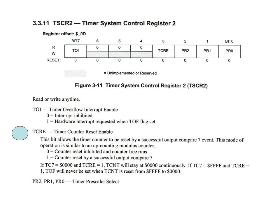
Other Timer Options Force Output Action of Selected Channels to Occur Immediately Use Successful Channel 7 Condition to Cause Other Selected Channel Outputs to Take on Specified Values “Pulse Accumulator” Mode for Implementing Event Counter or Counter with Gated Clock Let Two Counters Share an Input Pin for Detecting an Input Condition (rise,fall, or toggle)
")
20
Timer Compare Force Register

21
CFORC Example // Channel 6, 3, 2, 0 are selected as Outputs CFORC = 0x05; // Force Output Actions on Channel 0 and 2 // Does not set flags for interrupt request // CFORC = 0x44; // Force Output Actions on Channel 3 and 6 // Does not set flags for interrupt request

22
Output Compare on Channel 7 Option of sending new values to all or any subset of Output Pins OC7M Selects Output Pins OC7D Select New State of Selected Pins Can Reset TNCT if TCRE=“1”

23
Output Compare 7 Mask Register

24
Output Compare 7 Data Register

26
Example of Application of “Output Compare on Channel 7”: Generate Pulse Width Modulation (PWM) Signals Period Can Be Specified by OC7 Width of Pulse Generated at Output I Can Be Specified by OCi
 Signals Period Can Be Specified by OC7 Width of Pulse Generated at Output I Can Be Specified by OCi")
27
0 0x4000 0x8000 0xC000 0x4000 0x8000 0xC000 0 TCNT 0 TCNT 0 OC7 OC4 OC2

28
Example OC7 and TCRE=1 TIOS = TIOS | 0x94 ;//Select Channel 2, 4, 7 as Outputs OC7M = 0x14; // Select Channel 4 and 2 OC7D = 0x04; // Clear Channel 4 and Set Channel 2 TC7 = 0xC000; TC4 = 0x4000; TC2 = 0x8000; TCTL1= (TCTL1&0x3C) | 0x41; //0b0100 0001 - Ch 7 and 4 // TCTL1 = 01xx xx01 - toggle Ch 7 and 4 TCTL2= (TCTL2&0xCF) | 0x10; //0b0001 0000 - Ch2 // TCTL2 = xx01 xxxx - toggle Ch 2 TSCR2=0x09; // 0b00001001 – TCRE=1, Prescale=1 “Alarm Clock” values for Channels 2, 4, 7
 | 0x41; //0b Ch 7 and 4 // TCTL1 = 01xx xx01 - toggle Ch 7 and 4 TCTL2= (TCTL2&0xCF) | 0x10; //0b Ch2 // TCTL2 = xx01 xxxx - toggle Ch 2 TSCR2=0x09; // 0b – TCRE=1, Prescale=1 Alarm Clock values for Channels 2, 4, 7")
29
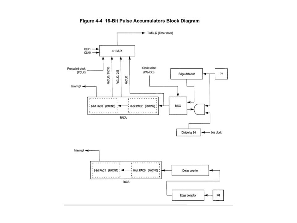
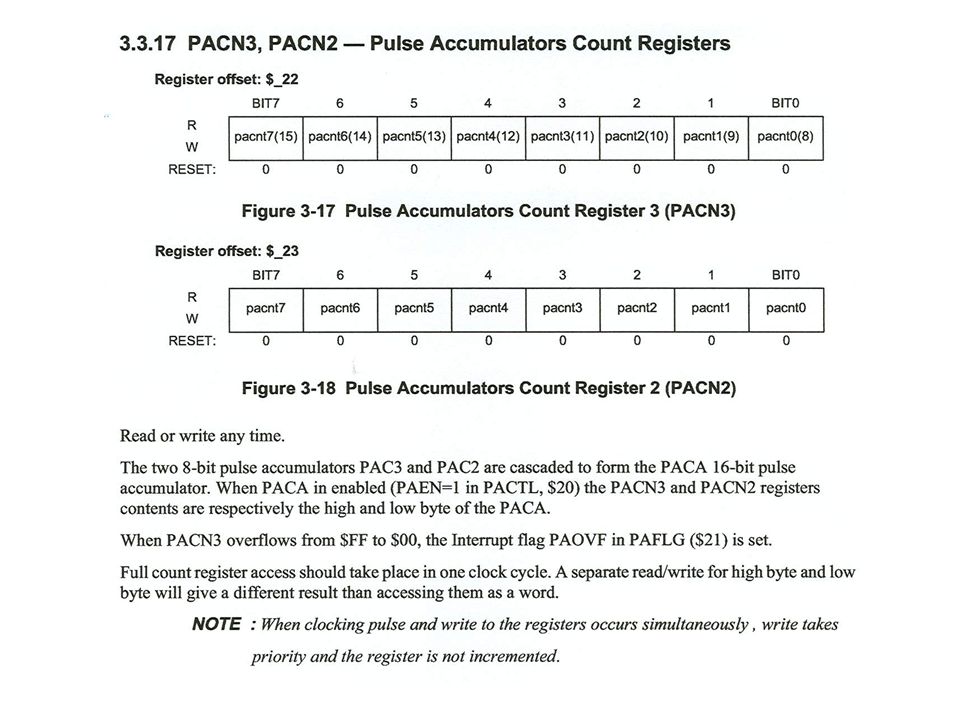
Pulse Accumulators 4 8-bit Pulse Accumulator –PAC0, PAC1, PAC2, PAC3 –Pin 0, 1, 2, and 3 of Port T serve as inputs for PACO, PAC1, PAC2, and PAC3 Accumulators are incremented on selected edge on pin TCTL4 selects edge detector algorithm –Rise, fall, either

35
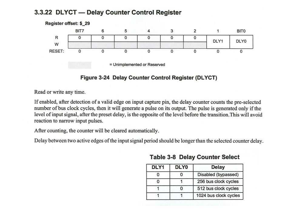
Delay Algorithm If 0->1 is selected edge, then input must be 1 after delay for Pulse Accumulator to be incremented If 1->0 is selected edge, then input must be 0 after delay for Pulse Accumulator to be incremented

36
Pulse Accumulator Enable

38
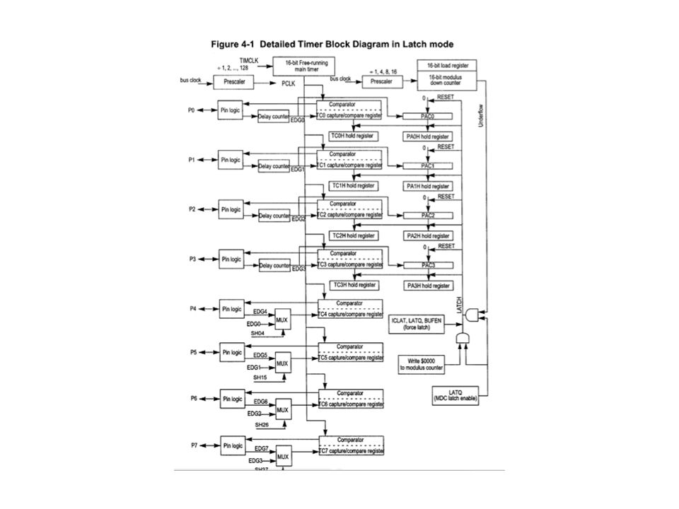
Modulus Down Counter 16-Bit Down-Counter That Can Be Initialized to Any 16-Bit Value When counter reaches 0x0000: - It sets a flag and can cause an interrupt - If is reloaded with its starting value and starts counting down again - In “Latch Mode,” values in the 8-bit Pulse Accumulators and 16-bit values in Input Capture Registers are latched into their holding registers, and the the 8-bit Pulse Accumulators are cleared.

39
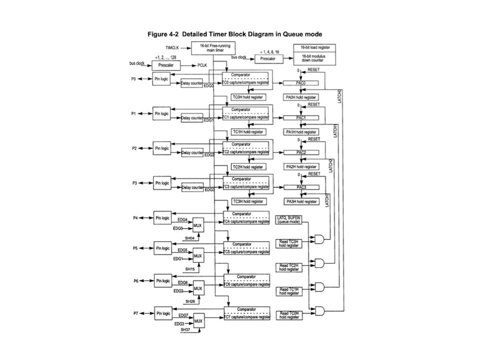
Buffered Mode Holding registers for Input Capture and Pulse Accumulators are enabled. Permits 2 input captured values prior to interrupt Enabled by setting BUFEN=“1” in ICSYS Channels 0, 1, 2, and 3 support Buffered Mode

40
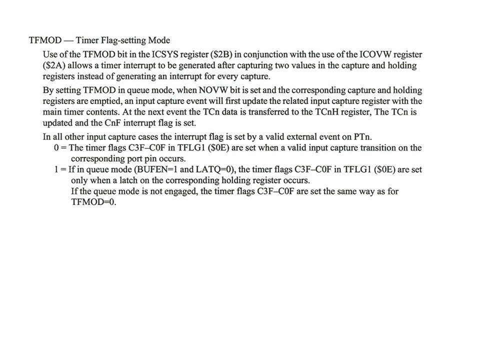
Buffered Mode (cont) Latching mode controlled by LATQ bit in ICSYS - LATQ = 0: Queue Mode: Latch on second edge (second pulse) - LATQ = 1: Latch Mode: Latch when Modulus Down Counter = 0 Note: When LATQ = 1 in Buffered Mode, a latching operation can be forced by setting a “1” to the ICLAT in the MCCTL control register.
 Latching mode controlled by LATQ bit in ICSYS - LATQ = 0: Queue Mode: Latch on second edge (second pulse) - LATQ = 1: Latch Mode: Latch when Modulus Down Counter = 0 Note: When LATQ = 1 in Buffered Mode, a latching operation can be forced by setting a 1 to the ICLAT in the MCCTL control register.")
41
SH37 – Pin 3 in input to Channel 3 and 7 concurrently SH26 – Pin 2 is input to Channel 2 and 6 concurrently SH15 – Pin 1 is input to Channel 1 and 5 concurrently SH04 – Pin 0 is input to Channel 0 and 4 concurrently

42
1 = Latch Mode is enabled. Latching occurs when modulus down-counter reaches zero or a zero is written into the count register MCCNT. When a latching event occurs, the contents of the Input Capture Registers and the 8-bit pulse accumulators are transferred to their Holding Registers and the 8-bit Pulse Accumulators are cleared.

Similar presentations

>")
, No Bidirectional.>")


 are nearly identical. Differences: -TCNT0 can run off an external 32Khz clock (Tosc) or the.>")


 are identical in function. Three separate comparison registers exist. Thus, three separate.>")


.>")
>")
>")
, used to bring down the frequency to the desired level.>")