Download presentation
Presentation is loading. Please wait.

1
Small Signal Model PNP Transistor Section 4.1-4.4,4.6

2
Schedule 92/11TuesdayPhysics of a BJT4.1-4.3 L2/11TuesdayMeasure Beta of a transistor 102/13ThursdayPNP 4.5 112/18TuesdayBJT in saturation mode4.5 L2/18Tuesday BJT in saturation/BJT implementation of an NAND gate 122/20ThursdaySmall Signal model [homework: small eq. circuit, (PNP)] 4.4,4.6
] 4.4,4.6.")
3
Overview

4
Review

5
Small Signal Model Section 4.4

6
Schematic of an Audio Amplifier Microphone produces a small signal. How does the amplifier circuit respond to a small change in the input signal? How is the analysis performed? Small signal model

7
Small Signal Analysis (For a Circuit You have not Seen Before) 1.Replace each ideal DC voltage source with a small signal ground. 2.Replace each ideal DC current source with an open circuit. 3.Replace each transistor by its small signal model 4.Analyze the small signal equivalent circuit.

8
Small Signal Analysis (For a Circuit You have not Seen Before) 1.Analyze the Circuit by Inspection
 1.Analyze the Circuit by Inspection")
9
Voltage Source DC Voltage Source in Small Signal Analysis R S should be 0 for a good battery!

10
Current Source R S should be infinity for a good battery!

11
Small Signal Model (NPN)(PNP) Statements that are always true for both NPN and PNP. 1.r π is between B and E. 2.the direction of the dependent current source always points from the collector to emitter. 3. r o is always between B and C.

12
Question Replace Q1 and Q2 by their small equivalent circuit.

13
Answer

14
Question

15
Answer

16
Derivation of the Small Signal Model

17
Change in the Collector Current Due to a Small Change in Base-Emitter Voltage If a signal changes the base-emitter voltage by a small amount, how much change is produced in the collector current ?

18
Derivation of Transconductance If a signal changes the base-emitter voltage by a small amount, how much change is produced in the collector current ? Small signal model of Q1

19
But there is something else…. A change in V BE creates a change in base current! Small signal model

20
Example 4.10 Signal Generated By a microphone Small Signal Equivalent Circuit V BE =800 mV β=100 I S,Q1 =3 x 10 -16 A Question: If a microphone generates a 1 mV signal, how much change is observed in the collector and base current ?

21
A Simple Amplifier Determine the output signal level if the microphone produces a 1 mV signal.

22
AC Ground The voltage produced by a voltage source is constant. The small signal model is concerned only with changes in quantities. Therefore, a DC voltage source must be replaced with a ground in small signal analysis.

23
Example Small Signal Model

24
Summary

25
Output Resistance Due to Early Effect A larger reverse bias voltage leads to a larger BC depletion region. The effective base width (WB) is reduced. The slope of the electron profile increases. I C increases as VCE is increased.
 is reduced. The slope of the electron profile increases. I C increases as VCE is increased..")
26
Early Effect

27
James M. Early

28
Modeling of Early Effect

29
What Doesn’t Change with Early Effect ?

30
Modification of the Small Signal Model

31
Slides to Cover During the Lab

32
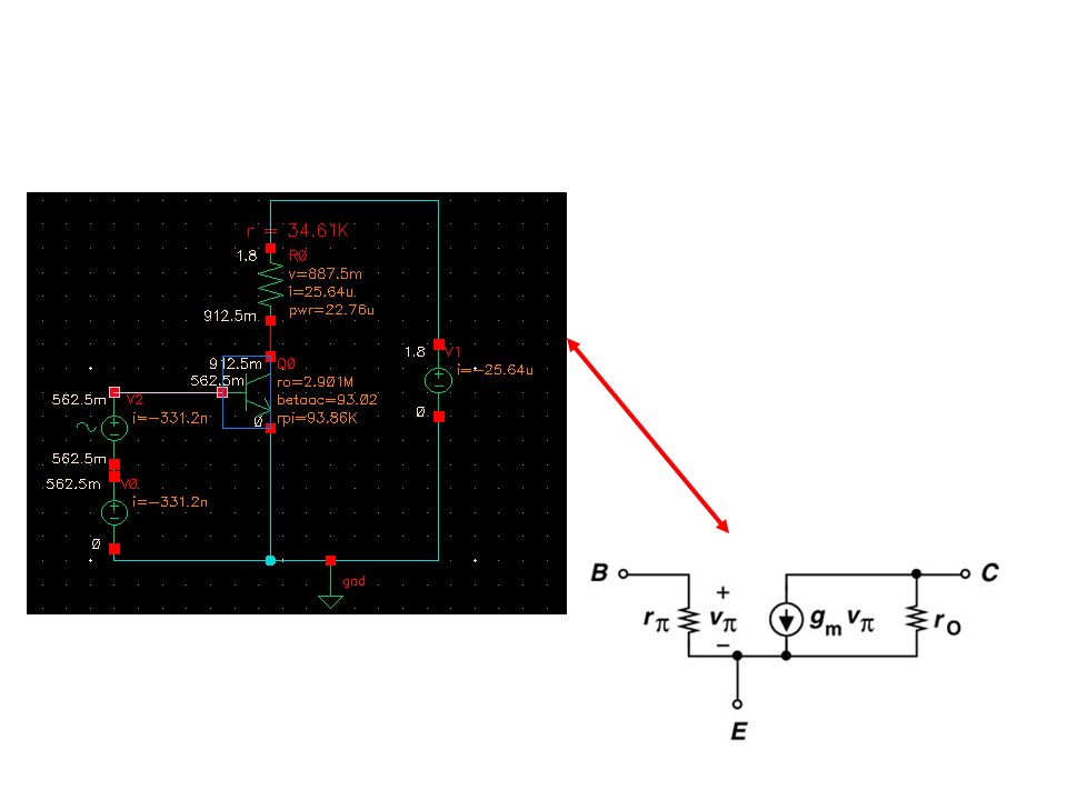
A Simple Cadence Example

33
Assumption Assume that 1.The DC at Vout is 0.9 V 2.g m =1 mS Gain is approximately equal to –g m R C. Bias current is I C =g m V t R=(1.8V-0.9V)/26uA=34.6 Kohms Gain is -34.6.
/26uA=34.6 Kohms Gain is")
34
DC Bias of the Amplifier

35
Sweep the Base Voltage to Get the IC=26 uA

36
Display the Transconductance

37
Display Transconductance

38
Verify Transconductance (1)
")
39
Verify Transconductance (2)
")
40
Transconductance VBIC 562.5 mV25.64 uA 563.5 mV26.64 uA ∆VBE1 mV ∆IC1 uA gm=∆VBE/∆IC1 mS

41
Introduce a Small Signal

42
Calculate Peak to Peak Voltage

44
Peak to Peak Voltage=67.78 mV 67.78 mV/2=33.9

Similar presentations

 Amplifiers>")


 – PNP transistor (structure, operation, models) BJT Amplifiers –>")
 – Transconductance – Small-signal model – The Early effect – BJT.>")

>")


. OUTLINE – Transconductance – Small-signal model – The Early effect – BJT operation in saturation mode Reading: Chapter 4.4.3-4.5.>")
 Tai-Cheng Lee Electrical Engineering/GIEE, NTU.>")
 L3/4Tuesday small signal model from Cadence,>")
. Still remember about BJT? The emitter current (i E ) is the sum of the collector current (i C ) and the base.>")
