Download presentation
Presentation is loading. Please wait.

1
Determining and Forecasting Load Reductions from Demand Side Programs September 11-12, 2007 Presented by: Bill Bland, V.P. Consulting, GoodCents Liza Thompson, Supervisor-Load Research, GoodCents

2
Introduction to Sample Design Sample Size Determining Sample Size General formula N=CV 2 /(D/Z) 2, where CV is coefficient of variation, D is percent accuracy desired, and Z is the standard normal deviate for the confidence level desired, Z=1.65 for 90% confidence, 1.96 for 95% confidence
 2, where CV is coefficient of variation, D is percent accuracy desired, and Z is the standard normal deviate for the confidence level desired, Z=1.65 for 90% confidence, 1.96 for 95% confidence")
3
Introduction to Sample Design Sample Size Determining Sample Size Example, 100,000 AC, estimate connected load CV estimate is 0.5 What sample size is necessary to know average connected load to within 10% at 90% confidence? N=CV 2 /(D/Z) 2, N=(0.5) 2 /(0.1/1.65) 2 N=68
 2, N=(0.5) 2 /(0.1/1.65) 2 N=68.")
4
Introduction to Sample Design Sample Size

5
Determining Sample Size Problems encountered in Research –No estimate of Population CV available –Solution, Use a correlated readily available variable- almost always billed kWh use –For AC load Management, recommend using July or August kWh use

6
Introduction to Sample Design Sample Size Determining Sample Size If we have population data available on a correlated variable such as billed kWh or AC connected load, we can use an alternate formula for sample size

7
Introduction to Sample Design Sample Size Determining Sample Size N=(1-R 2 )*CV 2 /(D/Z) 2 Where R is an estimate of the correlation of AC load and August billed kWh and CV is the coefficient of variation of August billed kWh
*CV 2 /(D/Z) 2 Where R is an estimate of the correlation of AC load and August billed kWh and CV is the coefficient of variation of August billed kWh")
8
Introduction to Sample Design Sample Size

10
AC Maximum Demand versus August kWh- R=0.5833 using actual End Use LR data, Assume CV of August kWh=0.75 N=(1-R 2 )*CV 2 /(D/Z) 2 N=(1-.5833 2 )*153 N=101
*CV 2 /(D/Z) 2 N=( )*153 N=101")
11
Introduction to Sample Design Sample Size Note on CV Estimates CV for Residential Class varies widely –CV Examples- 500,000 population- 0.82 –700,000 population – 0.6 –Calculate CV from Actual Billing Records

12
Introduction to Sample Design Sample Size Note on Residential Sample Sizes, CV Estimates Typical sample size assuming CV of 0.75 is 150 Use of Regression Estimator typically reduces sample size to about 115 points assuming R=0.5

13
Introduction to Sample Design Stratification Stratification- Dividing the population into smaller groups with like variance We recommend stratification to improve the overall load reduction estimates

14
Introduction to Sample Design Stratification Stratification How to determine strata boundaries to minimize variance? Use method of Dalenius and Hodges (DH)
.")
15
Introduction to Sample Design Stratification

16
Introduction to Sample Design Allocation of Sample to Strata We now know our strata and we will assume a sample size of 150 Do we assume 50 sample points per strata? We use Neyman allocation to allocate to strata based on σ of design variable and number of units in each strata

17
Introduction to Sample Design Allocation of Sample to Strata

18
Introduction to Sample Design Test and Control Groups Dont we need a test and control group since this is basically an experiment to see the effects of load control on AC use? The problems with a test and control group involve cost to do the research and matching up customer demographics and usage patterns to get comparable groups

19
Introduction to Sample Design Test and Control Groups We prefer to use the test group as its own control, therefore we do not have to match up demographics and we only need one sample Customers will be controlled on some days and not controlled on others Comparison will be of AC or premise loadshapes on control versus no-control days We will use regression analysis to develop the control estimates from our sample

20
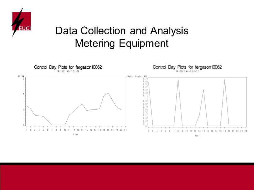
Data Collection and Analysis Metering Equipment Interval Load Data –Interval load data is necessary to develop load impact estimates for load management programs –We recommend the collection of at least hourly interval load data and if possible 15- minute data –The 15 minute data is averaged to get the hourly data

21
Data Collection and Analysis Metering Equipment Premise Metering –Meter Premise with interval meter –Estimate AC load reduction using premise data –Data must be collected monthly or can be collected real time if an AMR system is deployed –Costs $200.00- 300.00 per point

22
Data Collection and Analysis Metering Equipment Premise Metering –Utility may have interval meters for cost of service load study- no extra cost for equipment –Customer may not need to be recruited, Utility can gather data since utility owns meter –Load Reduction may be due to other equipment being turned off –Recommend sample size of at least 150 points if using premise meters only

23
Data Collection and Analysis Metering Equipment End Use Metering –Can Meter AC Compressor and other load managed end uses directly, highly accurate (99%) – Load Reduction Estimates are very accurate, smaller sample sizes (<100) can be used since CV of AC is less than CV of premise –Customer has to be recruited. Unit must be located next to Home load center( panel box), Unit needs a telephone line, either dedicated line or use customers line for downloads. May need to pay customer incentive
, Unit needs a telephone line, either dedicated line or use customers line for downloads. May need to pay customer incentive.")
24
Data Collection and Analysis Metering Equipment End Use Metering –Can also gather indoor temperature data and premise data –Cost per site for installation, equipment and 12 months of data collection is $2,000- $3,000 or more per point

25
Data Collection and Analysis Metering Equipment

27
Run Time Data Collection This involves a low cost device (<$100) that senses the on and off time of the compressor Data must be collected on site and downloaded to a shuttle once a month A large sample size is recommended due to high failure rate (15-20%) of data collection
 that senses the on and off time of the compressor Data must be collected on site and downloaded to a shuttle once a month A large sample size is recommended due to high failure rate (15-20%) of data collection")
28
Data Collection and Analysis Metering Equipment Run Time Data Collection failure is usually due to improper placement of the equipment or other equipment interfering with the signal This data requires more analysis time since the on-off time must be converted to kW, Data is discontinuous

29
Data Collection and Analysis Characteristics Data Characteristics data should be collected at each home –Necessary Data AC/ WH Nameplate, Make, Model, Serial Number Total Square Footage Indoor Daytime Thermostat Setting –Like to Have Number of Floors (square footage of each if available) Number of people in household Outdoor Construction
 Number of people in household Outdoor Construction")
30
Data Collection and Analysis Weather Data We have found that NWS or CMS data for the nearest station is preferable to data collected at the site. This is because site data is not collected using NWS/CMS standards. Daily and Hourly data can be used in the modeling process. We typically use Daily maximum temperature data. Indoor temperature Data is useful if end use metered data is available.

31
Data Collection and Analysis End Use Database The interval load, weather,control and characteristics data must be combined into one database for analysis. We recommend careful review of the database to ensure that the various files have been merged correctly before beginning modeling. Plots of data are helpful in identifying problems. We recommend and use SAS ® for data analysis, graphics and modeling.

32
Data Collection and Analysis Regression Modeling Our methodology is to develop a model from a sample of customers with interval data gathered on control and non-control days. The model is typically developed by strata and over a maximum outdoor temperature range for which AC load data is available.

33
Data Collection and Analysis Regression Modeling The SAS System 14:17 Thursday, December 8, 2005 8 The FREQ Procedure Table of control by Maximum Temperature control Maximum Temperature Frequency Percent Row Pct Col Pct 93 94 95 96 97 98 99 100 Total ƒƒƒƒƒƒƒƒƒˆƒƒƒƒƒƒƒƒˆƒƒƒƒƒƒƒƒˆƒƒƒƒƒƒƒƒˆƒƒƒƒƒƒƒƒˆƒƒƒƒƒƒƒƒˆƒƒƒƒƒƒƒƒˆƒƒƒƒƒƒƒƒˆƒƒƒƒƒƒƒƒˆ 0 1228 604 664 104 184 0 52 52 22963 4.37 2.15 2.36 0.37 0.65 0.00 0.19 0.19 81.73 5.35 2.63 2.89 0.45 0.80 0.00 0.23 0.23 86.97 47.34 37.03 50.00 30.46 0.00 50.00 100.00 ƒƒƒƒƒƒƒƒƒˆƒƒƒƒƒƒƒƒˆƒƒƒƒƒƒƒƒˆƒƒƒƒƒƒƒƒˆƒƒƒƒƒƒƒƒˆƒƒƒƒƒƒƒƒˆƒƒƒƒƒƒƒƒˆƒƒƒƒƒƒƒƒˆƒƒƒƒƒƒƒƒˆ 1 184 672 1129 104 420 288 52 0 5134 0.65 2.39 4.02 0.37 1.49 1.03 0.19 0.00 18.27 3.58 13.09 21.99 2.03 8.18 5.61 1.01 0.00 13.03 52.66 62.97 50.00 69.54 100.00 50.00 0.00 ƒƒƒƒƒƒƒƒƒˆƒƒƒƒƒƒƒƒˆƒƒƒƒƒƒƒƒˆƒƒƒƒƒƒƒƒˆƒƒƒƒƒƒƒƒˆƒƒƒƒƒƒƒƒˆƒƒƒƒƒƒƒƒˆƒƒƒƒƒƒƒƒˆƒƒƒƒƒƒƒƒˆ Total 1412 1276 1793 208 604 288 104 52 28097 5.03 4.54 6.38 0.74 2.15 1.03 0.37 0.19 100.00

34
Data Collection and Analysis Regression Modeling A model we typically use assumes AC use is determined by the temperature difference between the maximum daily temperature and the daytime thermostat setting squared multiplied by the size of the AC compressor in kW Models are developed by AC size strata used in the sample design process

35
Data Collection and Analysis Regression Modeling ACLOAD(Hour t, SiteJ) =A+B1*controlmaxmaxt2:(ACMaxkW(site J))*(0=no control in hour t, 1=control in hour t)*(max temperature-thermostat setting)**2 +B2*maxacdb2:(ACMaxkW(site J))*(max temperature-thermostat setting)**2 +B3*aclag:Hour 13 ACLoad(site(J))
 =A+B1*controlmaxmaxt2:(ACMaxkW(site J))*(0=no control in hour t, 1=control in hour t)*(max temperature-thermostat setting)**2 +B2*maxacdb2:(ACMaxkW(site J))*(max temperature-thermostat setting)**2 +B3*aclag:Hour 13 ACLoad(site(J))")
36
Data Collection and Analysis Regression Modeling A is the regression intercept and B1, B2 and B3 are regression coefficients determined during the modeling process. The B1 coefficient is the load reduction estimate for a 1 kW AC at hour t and a given temperature and thermostat setting. A total of 12 regressions were estimated. These are cross-sectional models and are estimated with all data from all sites for each strata and hour of control.

37
Data Collection and Analysis Regression Modeling Strata=1 (0-3 kW) HR=15 The REG Procedure Model: MODEL1 Dependent Variable: ac Number of Observations Read 1303 Number of Observations Used 1302 Number of Observations with Missing Values 1 Analysis of Variance Sum of Mean Source DF Squares Square F Value Pr > F Model 3 641.34869 213.78290 1611.81 <.0001 Error 1298 172.16052 0.13264 Corrected Total 1301 813.50920 Root MSE 0.36419 R-Square 0.7884 Dependent Mean 0.95349 Adj R-Sq 0.7879 Coeff Var 38.19574
 HR=15 The REG Procedure Model: MODEL1 Dependent Variable: ac Number of Observations Read 1303 Number of Observations Used 1302 Number of Observations with Missing Values 1 Analysis of Variance Sum of Mean Source DF Squares Square F Value Pr > F Model <.0001 Error Corrected Total Root MSE R-Square Dependent Mean Adj R-Sq Coeff Var")
38
Data Collection and Analysis Regression Modeling Strata=1 (0-3 kW) HR=15 The REG Procedure Model: MODEL1 Dependent Variable: ac Parameter Estimates Parameter Standard Variable DF Estimate Error t Value Pr > |t| Intercept 1 0.12832 0.02378 5.40 <.0001 controlmaxmaxt2 1 -0.00032607 0.00003430 -9.51 <.0001 maxacdb2 1 0.00018540 0.00004344 4.27 <.0001 aclag 1 0.99087 0.01595 62.11 <.0001
 HR=15 The REG Procedure Model: MODEL1 Dependent Variable: ac Parameter Estimates Parameter Standard Variable DF Estimate Error t Value Pr > |t| Intercept <.0001 controlmaxmaxt <.0001 maxacdb <.0001 aclag <.0001")
39
Data Collection and Analysis Regression Modeling

40
Mean AC Size, Thermostat Settings By Strata Daytime AC Size Thermostat StratakWTonsSetting 12.411982.2163474.3256 23.553883.1000474.7773 36.032145.1929975.0606

41
Data Collection and Analysis Regression Modeling A sample calculation for strata 3 for hour 17 for a temperature of 98 Degrees is shown below using data from Tables above. Control Coefficient (controlmaxmaxt2) -0.000490264 Temperature- 98 Degrees Daytime Thermostat Setting- 75.0606 Average Connected AC kW- 6.03214 Control Estimate= -0.000490264*(98-75.0606)*(98-75.0606)*6.03214 = -1.5562 kW.
 Temperature- 98 Degrees Daytime Thermostat Setting Average Connected AC kW Control Estimate= *( )*( )* = kW..")
42
Data Collection and Analysis Regression Modeling Strata 1 Weighted Control Estimate = -.5195 kW *.426521=-.22155 kW Strata 2 Weighted Control Estimate = -0.9037 kW *.366568= -.33129 kW Strata 3 Weighted Control Estimate = -1.5562 kW *.206911= -.32197 kW Population Weighted Average Control Estimate for Hour 17, Maximum Daily Temperature 98 Degrees= -.87481 kW at Customers meter.

43
Data Collection and Analysis Testing the Model Statistical Validity –Do coefficients have the right sign? –Are coefficients significant, T>1.65? Do the results make sense? –Is the control too much >average connected load times cycling percentage? –Is the control too small <<average connected load times cycling percentage?

44
Data Collection and Analysis Model Accuracy The stratified regression coefficients can be used to develop an estimate of the accuracy of the load reduction estimate by calculating the overall variance of the control estimate.

45
Forecasting Load Reductions Current Forecast The results of the regression model can be used to forecast current load reductions The output is typically a time-temperature matrix of load reductions The weighted load reduction mean estimate for each control hour is multiplied by the number of program participants

46
Forecasting Load Reductions Current Forecast

47
The forecast is only valid over the temperature range that the model was estimated over This may be an issue if you have only one year of history with maximum temperatures of say 93 degrees and you need estimates up to 100 degrees

48
Forecasting Load Reductions Thank You Contact Information bill.bland@goodcents.com 800-653-3445 X1067 Cell 678-409-2798 liza.thompson@goodcents.comiza.thompson@goodcents.com 800-653-3445 X1059

Similar presentations


 Class 9 Financial Management, 15.414.>")


